Basic concept
The Zetec-E engine is a four-cylinder, in-line, 16-valve DOHC engine. The 16-valve cylinder head provides better filling quality, especially at high engine speeds.
The cylinder head is made of aluminum alloy while the cylinder block is made of cast iron.
Center Timing Belt Cover/Engine Front Mount Bracket
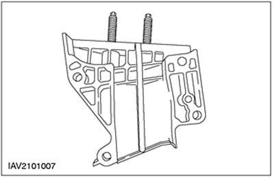
The new timing belt cover is additionally reinforced with a vertical support. This means that in order to install a new timing belt, the timing belt center cover and thus the front engine mount must be removed.
Cylinder head
The combustion chamber
The spark plug, located in the center of the roof-shaped combustion chamber, ignites the air-fuel mixture in the combustion chamber. The central location of the spark plug ensures an even distribution of the flame front throughout the combustion chamber, thus simultaneously reducing the tendency of the engine to knock.
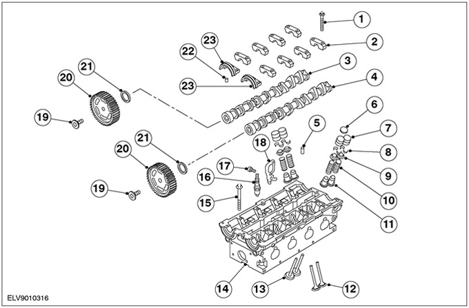
Valve mechanism
The two camshafts are driven by a single drive belt, and each shaft acts on two valves per cylinder via adjustable tappets. Due to the flow of exhaust gases passing through the exhaust valves, these valves are exposed to very high temperatures. Exhaust valves have a special coating that allows them to better dissipate heat. Each valve is closed by its own valve spring. To adjust the valve clearances, it is necessary to replace the shims in the valve lifters. Gaskets are available in 52 different thicknesses. The thickness of the adjusting shim is stamped on its back side in the form of a number corresponding to the thickness of the shim with an accuracy of hundredths of a millimeter (for example: number 222 = 2.22 mm). Due to the limited space in the cylinder head, the camshaft must be removed to replace the shims. In order to avoid the need for more than one removal and installation of the camshaft, absolute precision is required when performing the adjustment procedure. The camshaft cams are offset from the centers of the valve lifters. As a result, at an engine speed of approximately 3000 rpm, the valve lifters begin to rotate, and this rotation is transmitted to the valves. The rotation of the valves is desirable because it leads to a uniform seating of the valves in their seats and prevents the valves from running in the same position and leaking in the valves.
| Pos. | Spare Part No | Name |
| 1 | - | Camshaft bearing cap bolt |
| 2 | - | Camshaft bearing cap |
| 3 | - | intake camshaft |
| 4 | - | exhaust camshaft |
| 5 | - | Oil gallery plug |
| 6 | - | Gasket for adjustment (shim) valve clearance |
| 7 | - | valve tappet |
| 8 | - | Rusk |
| 9 | - | Valve spring plate |
| 10 | - | valve spring |
| 11 | - | Valve stem oil seal |
| 12 | - | exhaust valves |
| 13 | - | intake valves |
| 14 | - | cylinder head |
| 15 | - | Cylinder head bolt |
| 16 | - | Spark plug |
| 17 | - | Engine lift eye bolt |
| 18 | - | Engine lifting eye |
| 19 | - | Camshaft Pulley Bolt |
| 20 | - | Camshaft pulleys |
| 21 | - | Oil seals for distribution shafts |
| 22 | - | Guide sleeve for front camshaft bearing cap |
| 23 | - | Front camshaft bearing cap |
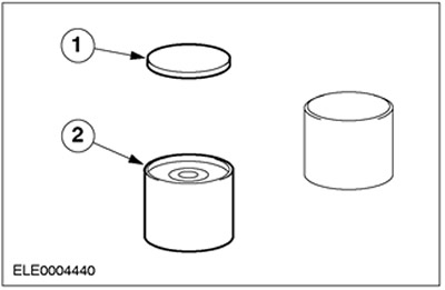
Mechanical pusher
| Pos. | Spare Part No | Name |
| 1 | - | Adjusting gasket (shim) (installed on the top of the pusher) |
| 2 | - | Mechanical pusher |
- In the new generation Zetec-E engines, hydraulic tappets can also be replaced with mechanical ones. This is achieved through the use of high quality materials and optimization of the cam profile.
- The degree of valve wear is so small that before passing a run of 150,000 km (90,000 miles) there is no need to check and adjust valve clearances.
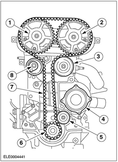
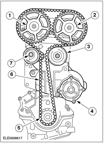
Timing belt drive (with lower intermediate pulley)
| Pos. | Spare Part No | Name |
| 1 | - | Intake camshaft with pulley |
| 2 | - | Exhaust camshaft with pulley |
| 3 | - | intermediate pulley |
| 4 | - | Coolant pump outer housing on cylinder block |
| 5 | - | intermediate pulley |
| 6 | - | crankshaft pulley |
| 7 | - | Modified timing belt guide |
| 8 | - | New spring-loaded timing belt tensioner with eccentric adjustment when removing and installing the timing belt |
Timing belt drive (without lower intermediate pulley)
| Pos. | Spare Part No | Name |
| 1 | - | Intake camshaft with pulley |
| 2 | - | Exhaust camshaft with pulley |
| 3 | - | intermediate pulley |
| 4 | - | Coolant pump outer housing on cylinder block |
| 5 | - | crankshaft pulley |
| 6 | - | Modified timing belt guide |
| 7 | - | New spring-loaded timing belt tensioner with eccentric adjustment when removing and installing the timing belt |
- The installation of the lower intermediate pulley was discontinued in January 1999.
- The timing belt should always be replaced after 150,000 km (90,000 miles) or after 10 years.
- The timing belt should always be replaced if it was removed during repair work.
Timing belt tensioner
CAUTION: Tighten the timing belt only when moving it in a counterclockwise direction.
The correct tension of the timing belt is ensured by the automatic belt tensioner. When installing a new belt, the tensioner moves to the base position (arrow (3) and mark (2) on one line). This basic setting is provided by one of the cams (4). Another (spring-loaded) The cam ensures that the correct belt tension is maintained while the engine is running. The belt tensioner moves up to 30 degrees off center in both directions.
NOTE: Do not retension the belt as there is a danger of exceeding the permissible angle of rotation in one of the directions. The basic setting of the belt tensioner is only applicable to a new timing belt. Retensioning the belt may cause it to wear or wobble.
It is no longer possible to check the basic setting after removing the adjusting tools and pins (the force from the valve springs is transmitted to the belt and changes the position of the belt tensioner).
Automatic timing belt tensioner
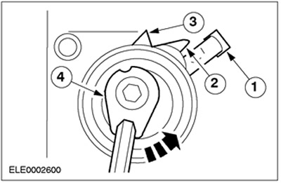
| Pos. | Spare Part No | Name |
| 1 | - | Bracket attached to sheet metal cover |
| 2 | - | mark |
| 3 | - | Arrow |
| 4 | - | Cam for basic setting |
Elements mounted on the cylinder head
Intake manifold
The new Zetec-E engines are equipped with an intake manifold made of fiberglass reinforced plastic. The intake manifold passages are arranged in such a way that they are the same length for each cylinder.
This provides the following benefits:
- Less heat transfer to the nozzles, thus preventing the occurrence of "steam plug";
- Lighter construction;
- Less fuel condensation on the walls of the intake manifold after a cold start;
- Less heating of the intake air when the engine is warm.
Elements installed on the intake manifold
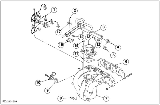
| Pos. | Spare Part No | Name |
| 1 | - | Injector plug |
| 2 | - | Bolt for clamping the fuel line |
| 3 | - | fuel manifold |
| 4 | - | Nozzle |
| 5 | - | nozzle holder |
| 6 | - | intake manifold gasket |
| 7 | - | Intake manifold |
| 8 | - | Quick coupler for brake booster vacuum hose |
| 9 | - | Idle speed control valve gasket (ISC valve) |
| 10 | - | ISC valve |
| 11 | - | Throttle Body Gasket |
| 12 | - | Fuel manifold bolt |
| 13 | - | throttle body |
| 14 | - | Bolt for fuel line bracket |
| 15 | - | Throttle Body Bolt |
| 16 | - | fuel line bracket |
| 17 | - | fuel line clamp |
Cylinder block
Crankshaft
The crankshaft is supported by five bearings and has a counterweight for each cylinder. The central main bearing has two thrust half rings that guide the crankshaft in the axial direction and determine its axial clearance.
Crankshaft bearings
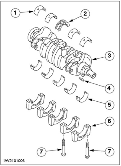
| Pos. | Spare Part No | Name |
| 1 | - | Insert of the radical bearing of the block of cylinders |
| 2 | - | Main bearing shell with thrust half-rings |
| 3 | - | Crankshaft |
| 4 | - | Segmented key for crankshaft pulley hub |
| 5 | - | Bearing shell, main bearing cap |
| 6 | - | main bearing cap |
| 7 | - | Main bearing cap bolt |
Connecting rod bearings
The connecting rod bearings are numbered from 1 to 4, which starts on the side where the timing belt is located. It is almost impossible to mix up the connecting rod bearing caps and connecting rods, because in the manufacture of the bearing caps, the connecting rods are simply cut off from the connecting rods. Therefore, the profile of the mating surface of each connecting rod bearing cap corresponds to only one of the connecting rods.
Reinforcing crankcase block
Lower crankcase
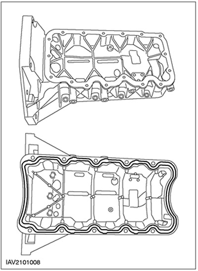
The crankcase reinforcement block is designed to dampen engine vibrations. This leads to a further reduction in the noise level in the vehicle interior. From 01.99 the seal between the lower crankcase and the cylinder block is a gasket with a metal bearing plate (vehicles up to 01.99 have a rubber seal).
Remote elements of the amplifying block of the engine crankcase
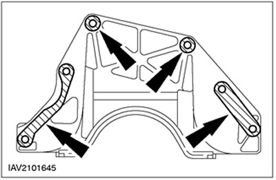
NOTE: From 01.99 only round spacers are used.
The spacers of the engine crankcase reinforcement block are used to compensate for increased clearances between the gearbox and the engine crankcase reinforcement block. For more information, refer to the Engine Assembly chapter available in this section.
Oil sump
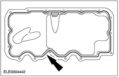
The engine is closed from below by an oil sump stamped from a metal sheet, which (crankcase) is attached directly to the crankcase reinforcement block of the engine. To ensure the tightness of the joint, a sealant roller 3 mm wide is used.
Engine management
Powertrain control module (RSM)
The Zetec-E engine is controlled by the PCM. To be able to do this, the PCM needs a lot of information on the current operating state of the engine. The PCM receives this information from numerous sensors.
RSM manages:
- fully electronic ignition system (EI),
- sequential electronic fuel injection (SEFI),
- air conditioning system combined with a cooling system.
Visitor comments