Caution: Always check first what parts are available before planning any major repairs. A Ford dealer, a good engine repair specialist, or a parts supplier may be able to offer alternatives that will allow you to overcome the shortage of parts if there is a problem.
1. Remove the cylinder head as described in Part A, section 11.
2. Remove the pan as described in Part A, section 12, then unscrew the two bolts and remove the oil receiver tube and mesh filter. Remove the O-ring from the mesh filter side (see figure 13.2, a, b).
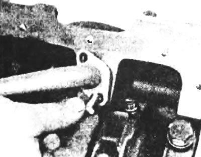
Figure 13.2a. Unscrew the two bolts and remove the tube with the mesh filter from the oil receiver.
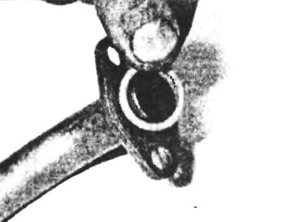
Figure 13.26. Remove the O-ring from the mesh filter.
3. Temporarily install the crankshaft pulley so that the crankshaft can rotate.
4. Make sure the connecting rod lower caps are numbered (or marked) to match the connecting rod and cylinder. If there are no marks, make your own so that you can ensure when reinstalling that each piston-connecting rod assembly not only fits its original cylinder, but is also correctly rotated in relation to it: the connecting rod cap must also fit the connecting rod and be correctly rotated.
5. Run your fingernail a quarter inch down from the top of each cylinder to feel for ridges at the top of the piston's stroke. If carbon deposits or cylinder wear have produced ridges, they must be completely removed with a special tool. Follow the manufacturer's instructions included with the tool. Attempting to remove the ridges before removing the piston and connecting rod may result in broken piston rings.
6. Rotate the crankshaft until two of the connecting rods are in the bottom position.
7. Loosen the connecting rod cap nuts by turning them simultaneously until they can be removed by hand. Remove the cover and bearing shell (see Figure 13.7). Do not drop the insert from the lid.
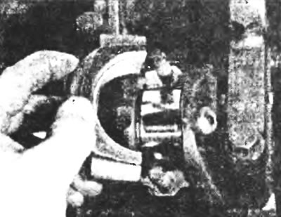
Figure 13.7. Remove the cap and bearing shell of the small end of the connecting rod.
8. Remove the rear main bearing shell and push the piston and connecting rod out through the top of the engine (see Figure 13.8). Use the wooden handle of a hammer to push the connecting rod bearing back slightly. If noticeable resistance is felt, double-check that all of the ridge has been removed from the cylinder.
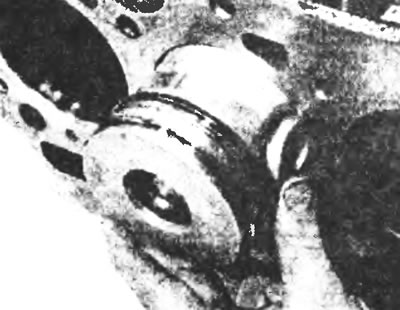
Figure 13.8. Push the piston and connecting rod out through the top of the engine.
9. Repeat the procedure for the remaining cylinders.
10. After removal, reassemble the caps and connecting rod liners with their connecting rods, tightening the nuts by hand. Leaving the old liners in place until assembly will protect the inner surface of the bearing from accidental damage. During assembly, new liners must be used.