Contents: Removal ↳ Installation ↳
Note: This is a complex operation, so please read this section carefully before you begin. To facilitate installation, always clearly mark disconnected hoses, wire connectors, vacuum lines, and fuel lines before removal so they can be reassembled correctly. For marking parts, masking tape or a paint striper work well. If necessary, take snapshots or sketch the locations of parts and brackets. When installing, it is necessary to install a new cylinder head gasket.
Removal
1. Disconnect the negative battery cable.
2. Drain the coolant as described in chapter 1.
3. Remove the cylinder head cover (see section 5).
4. Remove the intake manifold as described in chapter 4.
5. Remove the exhaust manifold (together with the turbocharger on a turbodiesel) as described in Chapter 4.
6. Disconnect the hose from the thermostat housing.
7. Disconnect the heater hose from the front surface of the cylinder head and release it from the clamps and brackets.
8. Disconnect the wiring connector from the thermostat housing. On early model engines, disconnect the thermostat sensor cable from the fuel pump.
9. Remove the clamps from the injector tube, then unscrew the nuts of the connecting tubes on the injectors and the fuel pump (see Figure 11.9). Use a second wrench to hold the injector if necessary while loosening the union nut. It is necessary to close open channels and connections with a plug or lid.
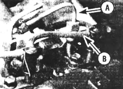
Figure 11.9. Remove the fuel injector delivery (A) and return (B) pipes.
10. Carefully remove the fuel injector delivery pipes, being careful not to bend or twist them during removal.
11. Disconnect the drain pipe between the injectors and the fuel pump and the drain pipes between the injectors.
12. Remove the fuel injectors as described in chapter 4.
13. Remove the valve train as described in section 10.
14. Access to the bolt securing the front surface of the cylinder head may be difficult due to the proximity of the temperature sensor unit. In this case, the temperature sensor unit should be removed.
15. Disconnect or move aside any hoses and fuel lines that may interfere with removal of the cylinder head.
16. Unscrew the bolts securing the cylinder head in the sequence shown (see Figure 11.16). Once all the bolts are removed, pull them out, then lift the cylinder head and remove the gasket. Since the gasket must always be replaced with a new one, it should be remembered that the bolts can be reused, but only three times, marking each time with a center punch or paint. If you don't know how many times the bolts have been used, they need to be replaced with new ones.
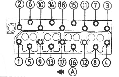
Figure 11.16. Sequence for loosening the cylinder head bolts: A - front of the engine.
17. The procedure for removing and performing routine repairs of the cylinder head is given in part B of this chapter. Every time the head is removed, it is necessary to remove carbon deposits from it and grind the valves.
Installation
18. Before installing the cylinder head, clean off all carbon deposits, dirt and old gasket residue from the mating surfaces of the head and cylinder block. Prevent dirt from entering the cylinder bores, oil and water passages; if this happens, remove the dirt. Clean the threads of the cylinder head bolts (if you do not install new bolts) and holes for them in the block. Remember that driving a bolt into a hole filled with oil or water can cause cracks in the block due to hydraulic pressure.
19. Make sure the new cylinder head gasket is the same type as the original one, then place the gasket on the top surface of the cylinder block by sliding it onto the pins (see Figure 11.19).
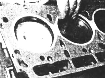
Figure 11.19. Install the cylinder head gasket on the guide pins.
20. Carefully lower the cylinder head to its original location, then insert the bolts and tighten them finger tight (see Figure 11.20).
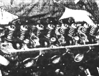
Figure 11.20. Carefully lower the cylinder head to its original location.
21. Tighten the bolts in three stages and in the correct order. First, tighten all bolts in the specified sequence to Stage 1, then tighten them in the same sequence to Stage 2. Once all bolts are tightened to Stage 2, tighten all bolts in sequence to the specified rotation angle (Stage 3). Where possible, use an angle gauge in Stage 3 (see figure 11.21, a, b, c). Mark the center of each bolt head with a punch or other mark once they are all tightened - see paragraph 16.
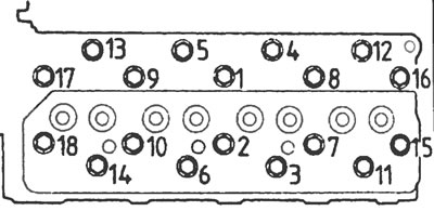
Figure 11.21a. Cylinder head bolt tightening sequence.
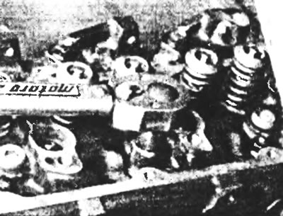
Figure 11.21b. First, tighten the cylinder head bolts with a torque wrench...
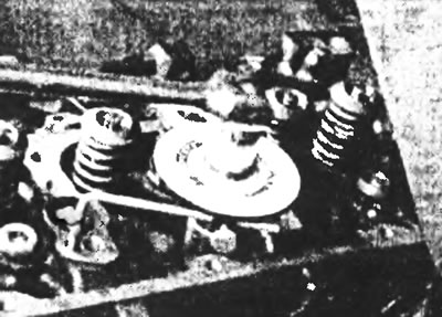
Figure 11.21c....then through a certain angle of rotation using a key with an angular scale.
22. Install the valve drive (see section 10).
23. Adjust the valve clearances (see section 9).
24. Install the fuel injectors (see chapter 4).
25. Connect the drain hose between the injectors and the fuel pump, and the drain tubes between the injectors. On the "banjo" connections (if any) install new copper washers.
26. Carefully install the injector delivery tubes in place, being careful not to bend or damage them during installation.
27. Remove the plugs used to close the open passages and screw the connecting tubes to the injectors and fuel pump. To hold the injector, use a second wrench if necessary.
28. Connect the electrical wiring connectors to the thermostat housing. On early model engines, connect the temperature sensor cable to the fuel pump and adjust it as described in chapter 4.
29. Connect the heater hose to the front surface of the cylinder head and secure it with support clamps and brackets.
30. Connect all pipes to the thermostat housing.
31. Install the intake and exhaust manifolds as described in chapter 4.
32. Install the cylinder head cover (see section 5).
33. Fill the cooling system with liquid (see Chapter 1).
34. Connect the negative battery cable.
35. Once the engine is running, check for fuel, oil, and/or coolant leaks from the various cylinder head connections.