Contents: Removal ↳ Installation ↳
Note: New gaskets, seals and o-rings will be required for installation.
Removal
1. Remove the crankshaft pulleys and the camshaft timing belt tensioner (see section 8).
2. Disconnect the high pressure oil supply pipe from the rear of the vacuum pump (on the back of the alternator) and the oil bypass hose from the oil pump housing (see Figure 13.2).
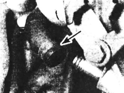
Figure 13.2. Disconnect the oil return hose (indicated by the arrow) from the oil pump housing.
3. After unscrewing the alternator fixing and adjusting bolts, remove the alternator and adjusting lever.
4. Unscrew the oil pump housing bolts in the reverse order to that shown (see Figure 13.20). After marking the position of the longer bolts, remove the shroud from the engine intermediate plate (see Figure 13.4).
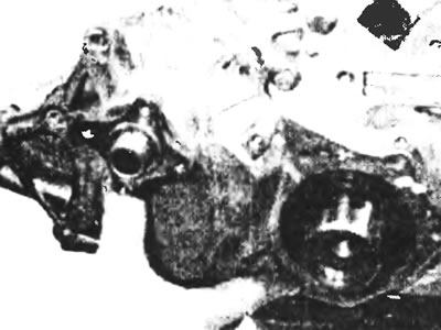
Figure 13.4. Remove the oil pump housing from the engine intermediate plate.
5. After removing the woodruff key from the crankshaft, remove the oil pump drive pinion (see figure 13.5, a, b).
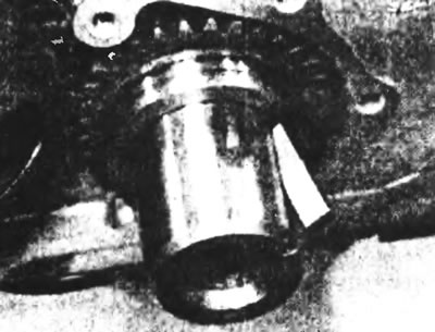
Figure 13.5a. Remove the woodruff key from the slot on the crankshaft...
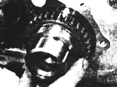
Figure 13.5b....and remove the oil pump drive gear.
6. Rotate the oil pump drive auxiliary gear so that the pump retaining bolts can be accessed through the slots in the auxiliary gear (see Figure 13.6).
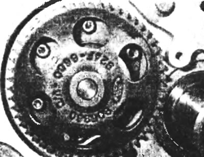
Figure 13.6. Rotate the oil pump auxiliary gear to access the bolts.
7. Using a socket and extension rod, loosen the retaining bolts and separate the oil pump assembly from the engine intermediate plate. Remove the two sealing rings from the pump mounting location in the cylinder block (see figure 13.7, a, b).
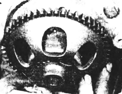
Figure 13.7a. After unscrewing the bolts, remove the oil pump block...
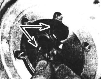
Figure 13.7b....and remove two sealing rings from the lubrication channels (indicated by arrows).
8. Thoroughly clean all parts and remove all traces of the old gasket from the mating surfaces.
9. Before installation, replace the front crankshaft oil seal located in the oil pump housing with a new one, (see section 15) and purchase new ones: casing gasket and oil channel sealing rings.
Installation
10. Clean the locations of the two sealing rings in the cylinder block and install new rings in the grooves of the lubrication channels of the cylinder block (see Figure 13.7,b).
11. Fill the oil pump with clean engine oil (see Figure 13.11) and install the pump on the intermediate plate, rotating it if necessary to align the bolt holes.
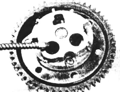
Figure 13.11. Before installation, fill the oil pump with clean engine oil.
12. After inserting the fixing bolts, tighten them to the specified tightening torque (see Figure 13.12).
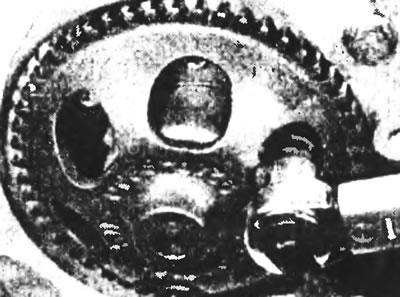
Figure 13.12. After inserting the fixing bolts, tighten them to the specified tightening torque.
13. Apply sealant to the inner surface of the oil pump drive pinion that faces the engine. Install the pinion on the crankshaft so that the oil seal groove faces outward (see figure 13.13,a,b).
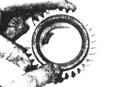
Figure 13.13a. Apply sealant to the surface of the pump drive gear...
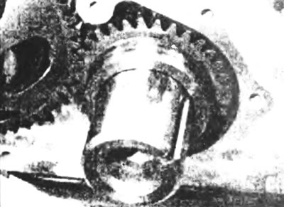
Figure 13.13b....and install the gear on the crankshaft so that the oil seal track faces outward.
14. Using a set of feeler gauges, measure the circumferential clearance of the oil pump gears at four equally spaced points. If this clearance exceeds the limits given in the Specifications, replace the pinion gear with a new one. If, even with a new pinion gear, the backlash remains excessive, replace the entire oil pump assembly.
15. Install the woodruff key onto the crankshaft.
16. Install the new oil pump housing gasket into the intermediate plate (see Figure 13.16).
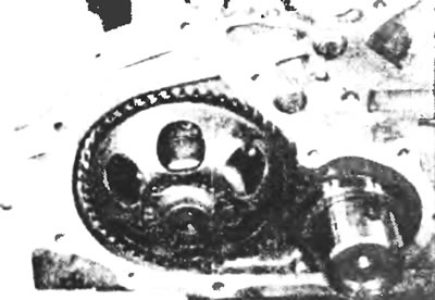
Figure 13.16. Place the new oil pump housing gasket on the intermediate plate.
17. The new oil seal for the oil pump housing must be provided with a plastic sleeve to protect the seal contact edge when installing the housing. If you don't have a shell, make a suitable replacement from a paper cup or something similar.
18. After liberally lubricating the contact lip of the oil seal, insert the protective sleeve into the oil seal from the rear so that the oil pump drive pinion pushes it out after the housing is installed.
19. Install the oil pump housing and remove the protective sleeve after the seal contact lip is seated on the oil pump drive pinion. Insert the retaining bolts into the corresponding holes marked during removal and tighten them by hand at this stage.
20. Now you need to make sure that the oil seal is precisely centered on the drive gear. Ford special tools #21-101 or #21-149 are ideal for this purpose. However, in practice, the movement of the housing within the holes of the fixing bolts is so small that the correct alignment of the housing can only be assessed visually. Once the housing is centered, tighten the retaining bolts to the specified torque in the order shown (see Figure 13.20).
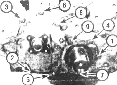
Figure 13.20 Tighten the oil pump housing bolts in the order shown.
21. Install the alternator and adjusting lever.
22. Connect the high pressure oil supply pipe to the rear of the vacuum pump and the oil return hose to the oil pump cover.
23. Install the camshaft timing belt tensioner and crankshaft pulleys as described in section 8.