Contents: For engines of all models except GLA ↳ For GLA model engine ↳ Checking the technical condition of… ↳
Disconnect the negative cable from the battery and drain the coolant. Remove the alternator drive belt.
For engines of all models except GLA
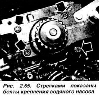
Turn the crankshaft until the EZMT marks are aligned and remove the toothed belt cover. Loosen the toothed belt tension and remove it. Drain the coolant. Disconnect the hoses going to the radiator and to the heater. Remove the toothed belt tensioner. Unscrew the four mounting bolts (Fig. 2.65) and remove the water pump.
Before installing the water pump, it is necessary to remove the remains of the old gasket from the mating surfaces, install a new gasket 3 (Fig. 2.66) and install the water pump.
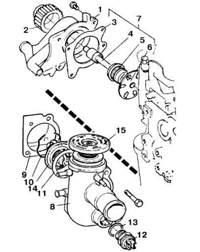 Fig. 2.66. Parts of the water pump and thermostat housing.
1 - water pump; 2 - toothed pulley of water pump drive; 3, 9 - gaskets; 4 — pump shaft with bearing; 5 - water pump cuff; 6 — impeller; 7 - Water pump repair kit; 8 — thermostat housing; 10 - retaining ring; 11 - rubber ring; 12 — electric fan switch sensor; 13 - fiber gasket; 14 — thermostat; 15 — thermostat housing plug.
Install the tensioner and put on the timing belt as described in the section "Camshaft and its drive". Install the timing belt cover, put on the alternator drive belt and tighten it. Connect the hoses to the radiator and heater, fill the system with coolant. Start the engine and check for leaks.
For GLA model engine
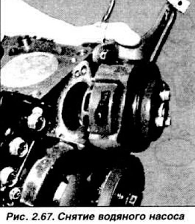
Clear access to the mounting bolts and remove the water pump pulley. Remove the water pump (Fig. 2.67), using a mallet with a plastic striker if necessary.
Remove the remains of the old gasket, check the condition of the parts. Before installing the new gasket, apply a layer of sealant such as Perfect Seal and install the water pump in the reverse order of its removal. Tighten the drive belt as indicated above.
Checking the technical condition of the water pump of the GLA engine
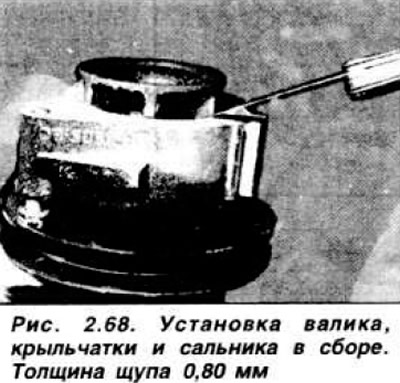
Install the pump on a special support and press the drive flange. Turn the pump over and knock out the impeller with the shaft and gland assembly. Press the impeller off the shaft and remove the gland. Clean and inspect the parts, replace the parts whose technical condition is unsatisfactory. Assemble the pump in the reverse order of disassembly, taking into account the following: the shaft should protrude beyond the drive flange by 1.5 mm. When pressing the shaft with gland and impeller assembly into the pump casing, ensure a gap of 0.80 mm between the impeller and the casing (Fig. 2.68).
(This publication was borrowed from the website fordbook.ru)