Removal
1. Remove the cylinder head cover as described in section 5.
2. Unscrew five M10 bolts and eight M8 bolts in sequence, then remove the valve drive assembly from the cylinder head (see Figure 10.2, a, b).
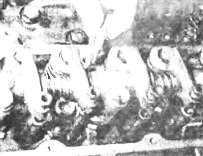
Figure 10.2,a. Unscrew the fixing bolts -
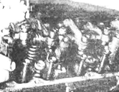
Figure 10.2, b....and remove the valve drive assembly from the cylinder head.
3. Remove the valve crackers, placing them on the numbered trays so that they can be installed in their original order during installation (see Figure 10.3).
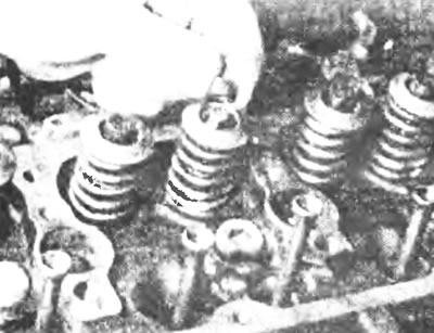
Figure 10.3. Remove the crackers from the valves.
4. Remove the valve lifter rods. To keep them in the correct order for installation, insert them into a piece of cardboard, numbering them 1 through 8 from the FRONT of the cylinder head (see Figure 10.4).
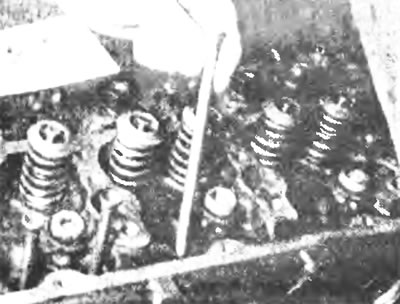
Figure 10.4. Remove the push rods...
Inspection
5. To remove the rocker arm shaft, unscrew the bolts securing the rocker arm supports, then remove all rocker arms, supports and coil springs from the shaft, but try to keep them in their original order for installation (see Figure 10.5, a, b).
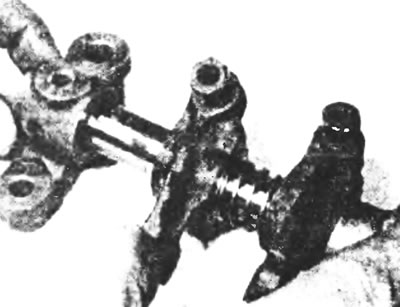
Figure 10 5,a. Remove the valve rocker arms, supports...
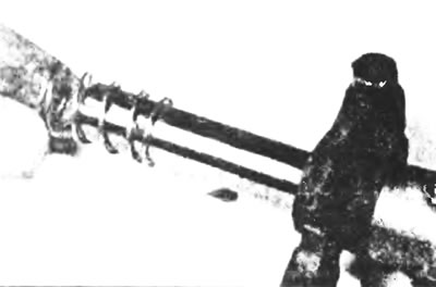
Figure 10.5, b....and cylindrical springs from the rocker arm axis.
6. Clean parts and inspect for signs of excessive wear or damage. Check that the oil holes in the axle are clean.
7. Check for wear or scoring on the shaft and on the part of the rocker arms that press on the valve heads. Replace worn parts if necessary.
8. Before installation, lubricate the rocker arms and axle with clean engine oil (see Figure 10.8).
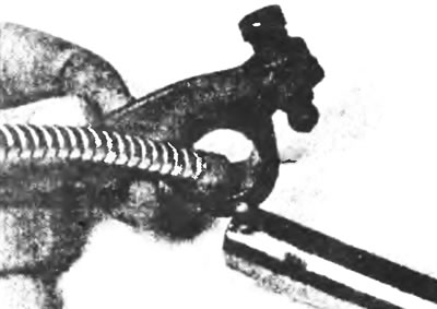
Figure 10.8. Lubricate the rocker arms and axle with clean engine oil before installation.
9. Install all supports, springs and rocker arms in their original position, checking the correctness of their relative position (see Figure 10.9).
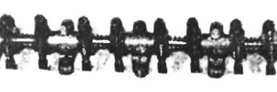
Figure 10.9. Valve drive assembly, note the correct placement of parts.
Installation
10. Lubricate the valve lifter rods and install them in their original order.
11. After installing crackers on each valve, lower the valve train assembly and simultaneously insert the adjusting screws. Once this block is installed, insert the tip of each rocker arm into the cup of the corresponding rod.
12. After inserting the bolts, gradually tighten them to the specified torque, tightening the M10 bolts first.
13. After adjusting the valve clearances as described in section 9, install the cover as described in section 5.