Contents: Inspection ↳ Replacement ↳
Inspection
1. Engine mounts rarely require special attention, but broken or worn mounts must be replaced immediately with new ones, otherwise additional stress will be placed on transmission components.
2. During inspection, the engine must be slightly raised to remove its weight from the mounts.
3. Apply the handbrake, then raise the front of the vehicle and lower it onto supports (see "Lifting the car with a jack and placing it on supports"). Place a jack under the oil pan, placing a large block of wood between the jack head and the oil pan, then carefully raise the engine just enough to take the weight off the mounts.
4. Check the condition of the fasteners - is the rubber cracked, hardened or separated from the metal parts. Sometimes the rubber cracks just below the center.
5. Check the relative offset between each mounting bracket and the engine or housing (using a large screwdriver or a lever, try to move the fasteners). If any movement is detected, lower the engine and tighten the mount fasteners.
Replacement
6. The engine mounts can be removed once the engine is supported using one of the following methods.
7. You can support the weight of the unit from below using a jack and a suitable wooden block between the jack head and the oil pan (to prevent damage) or from above, by attaching the lift to the engine. If the air filter is mounted on top of the engine, it should be removed to provide sufficient clearance for lifting the engine. In addition, it is necessary to remove the lower engine splash guard, if there is one.
8. Once the weight of the engine is adequately supported, the mounts can be unscrewed and removed. The following figures show the supports and associated components (see Figure 17.8, a-d). As the supports are disconnected and removed, the location and orientation of the supports and any associated equipment must be marked.
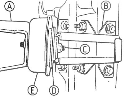
Figure 17.8,a. Engine mounting parts on models produced before 1992: A - Engine support bracket, B - Side member (side beam) chassis, C - Rubber suspension mount lock nut, D - Rubber support, E - Support cover
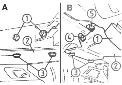
Figure 17.8,b. Engine mounting parts on models produced from 1992 to 1995:A - View of the outer side beam of the chassis; B - View of the inner side beam of the chassis; A1 - Tie bolts; B1 - Support cover; 2 - Engine support bracket; 3 - Lower engine support bracket fixing bolts; 4 - side fixing bolts of the engine support bracket; 5 - Upper engine support bracket fixing bolts.
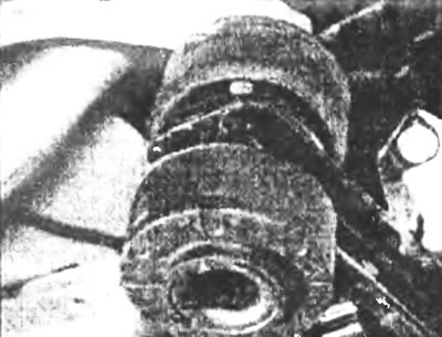
Figure 17.8, c. Rubber pad and bracket, which have been used since 1995.
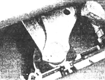
Figure 17.8, d. Nut for fastening the rubber cushion to the engine bracket, used since 1995...
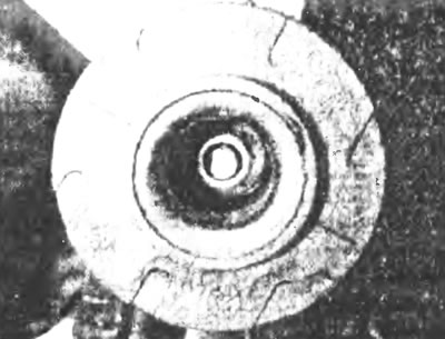
Figure 17.8, d.... and the nut securing the rubber support on the chassis support bracket (bottom view).
9. Installation of all fasteners in place is carried out in reverse order to the removal procedure. Make sure that the original sequence of fastening the washers and associated hardware is followed exactly.
10. Do not fully tighten the fastener clamps until all fasteners are in the required position. Check that the rubber of the fasteners does not warp or deform when the bolts and nuts are securely tightened.
[The text of the article was copied from the website: fordbook]