Removal
1. Access to the flywheel can be obtained either by removing the gearbox as described in chapter 7A or 7B, or by removing the engine as described in Part B of this chapter.
2. On models with a manual transmission, remove the clutch as described in Chapter 6.
3. Unscrew the 8 fixing bolts and remove the flywheel from the rear flange of the crankshaft. To prevent the flywheel from rotating (crankshaft) when removing bolts and later when installing, install a tool similar to the one shown (see Figure 16.3).
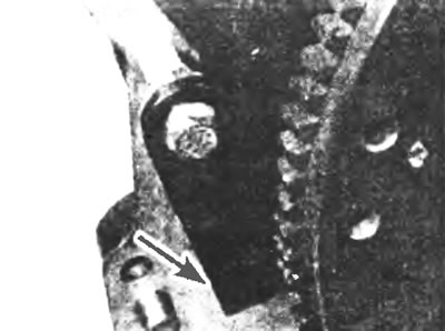
Figure 16.3. Homemade tool (indicated by the arrow) can be used to prevent the flywheel from rotating (crankshaft) when removing bolts.
Inspection
4. Check for broken or excessively worn teeth on the starter drive ring gear in the flywheel. If this is detected, the ring gear must be replaced, but since this is a complex task, it is best left to specialists.
5. The clutch friction surface on the flywheel must be carefully inspected for nicks, grooves or hairline cracks (caused by overheating). If such damage is found, the flywheel surface can be ground to renew it, provided that the balance is not disturbed. Resurfacing should be done by a specialist. If it is not possible to polish the surface, the flywheel should be replaced with a new one.
6. Carefully inspect the center punch marks on the heads of the fixing bolts. These bolts can be used a maximum of 6 times and (theoretically) they should be marked with a center punch each time they are removed. If five punch marks are visible or there is any doubt about the condition of the bolts, they should be replaced.
Installation
7. Check that the mating surfaces of the flywheel and crankshaft are clean before installation. Install the flywheel onto the crankshaft by inserting it onto the dowel pins and screwing in the bolts (see Figure 16.7).
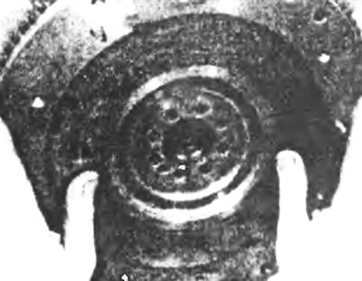
Figure 16.7. Install the flywheel onto the crankshaft, placing it on the mounting pins.
8. Tighten the bolts gradually in pairs in a diagonal sequence to the specified tightening torque. Please note that on 1992 and later models, bolts are tightened first to the specified Stage 1 torque, then through a specific rotation angle (Stage 2). Where possible, use an angle torque gauge to accurately tighten the threaded connection at Stage 2 (see Figure 16.8). After installation, it is necessary to make a mark on the bolt heads with a center punch or something else (see section 6).
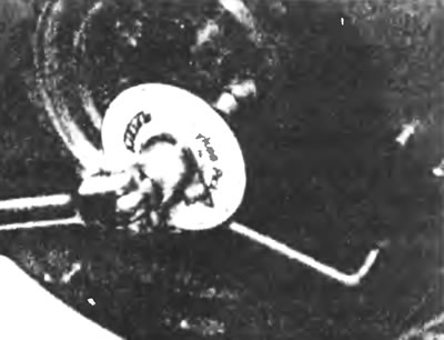
Figure 16.8. Tighten the bolts gradually in pairs in a diagonal sequence to the specified tightening torque.
9. After installing the flywheel in place, it is advisable to check its runout using a dial indicator (see Figure 16.9). If the flywheel runout exceeds the maximum value specified in Specifications, remove the flywheel and check the mating surfaces for damage. If the mating surfaces are found to be undamaged, the flywheel should be replaced with a new one.
10. On vehicles with a manual transmission, install the clutch assembly as described in chapter 6, then install the engine or gearbox.
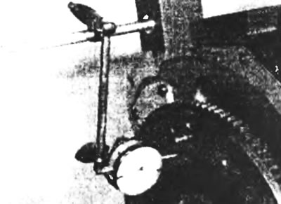
Figure 16.9. Check the flywheel runout with a dial indicator.
[Information for this article was taken from the website: FordBook.ru]