Contents: Removal ↳ Installation ↳
Note: The gearbox can be removed as a unit with the engine as described in Chapter 2B, then separated from the engine on site. However, if repairs are only needed on the gearbox or clutch, it is better to remove the gearbox itself from the bottom of the car. The latter method is described in this section. Removal and installation will require a jack and at least one assistant.
Removal
1. Disconnect the negative battery cable.
2. With the parking brake applied, jack up the front of the vehicle and support it securely on supports at a height that provides sufficient working clearance under the vehicle. On G and MT75 type gearboxes, place a suitable container under the drain plug and drain the transmission oil. When finished, replace the plug.
3. On vehicles with independent front suspension and a G or N type transmission, the front suspension crossmember will need to be lowered to provide sufficient clearance. To do this, first remove both front coil springs as described in Chapter 10. Place a powerful jack under the crossbar and jack it up without lifting it, just supporting its weight. Remove the two bolts on each side that secure the cross member to the body, then lower the jack and cross member approximately 100mm.
4. On engines with an air filter mounted directly on the intake manifold, remove the air filter as described in Chapter 4.
5. Remove the gear shift lever (see Section 2).
6. Remove the starter as described in Chapter 5.
7. Remove the propeller shaft as described in Chapter 8.
8. If installed, release the connectors and remove the lower engine cover and the two-piece housing covering the clutch housing (see Figure 7.8).
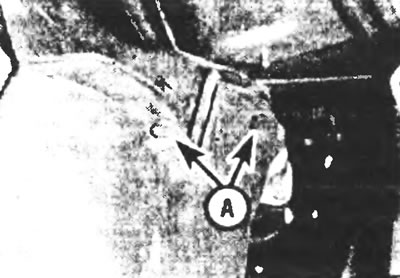
Figure 7.8. After releasing the fasteners (A) on both sides, remove both parts of the casing covering the clutch housing.
9. Disconnect the exhaust pipe from the manifold. On later models, for better access, it may be convenient to also disconnect the front exhaust pipe flange and remove the exhaust pipe completely.
10. Separate the rubber boot of the release fork from the clutch housing. Slide the inner cable out of the groove on the release fork and release the cable sheath from the clutch housing. Remove the rubber boot from the cable.
11. Disconnect the reversing light switch cable connector and move the cable to the side (see Figure 7.11).
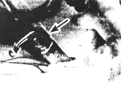
Figure 7.11. Disconnect the reverse light switch wiring connector (indicated by the arrow).
12. After unscrewing the retaining bolt, remove the speedometer drive cable retaining plate. Pull the speedometer cable out of the gearbox and move it to the side so that it does not interfere (see figure 7.12a,b).
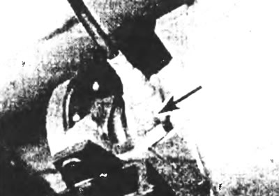
Figure 7.12,a. Unscrew the bolt (indicated by the arrow) and remove the speedometer cable retaining plate.
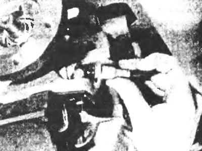
Figure 7.12, b....then pull the speedometer cable out of the gearbox housing.
13. If an electronic tachograph is installed, disconnect the tachograph wiring and move it to the side.
14. After unscrewing the bolts, remove the lower casing from the clutch housing.
15. Place a jack under the gearbox to support its weight.
16. Unscrew the single central bolt (gearboxes of types G and N) or two nuts (mT75 gearbox), securing the gearbox mount to the gearbox housing. Remove two bolts on each side and remove the transmission crossmember through the bottom of the car (see Figure 7.16).
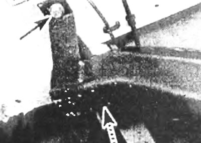
Figure 7.16. Remove the gearbox cross member by unscrewing two bolts on each side.
17. Remove the retaining bolts connecting the clutch housing to the engine, including the single bolts securing the engine support brackets. Please note that on some models, one of the bolts secures either the engine ground strap or the positive battery cable support bracket, and the top pair of bolts secure the fuel line bracket.
18. Support the engine sump with a second jack or blocks while the transmission is removed. When using a jack, place a large flat block between the jack head and the pan.
19. Check again that everything is disconnected and put aside. With the help of an assistant, move the transmission back and disconnect it from the engine. (Make sure that the box does not rest with all its weight on the drive shaft). If necessary, remove the clutch housing from the engine mounting pins.
20. Once the box is disconnected, lower it and pull it out through the bottom of the machine.
Installation
21. Installation is carried out in the reverse order of removal. Before connecting the gearbox to the engine, check that the clutch release bearing is installed correctly and apply a small amount of special grease to the gearbox input shaft. If you have replaced the clutch, it should be centered so that the transmission input shaft can enter the splines of the clutch driven disc and the pilot bearing at the rear of the crankshaft (see Chapter 6).
22. Once the box is connected to the engine, insert a pair of mounting bolts and install the crosspiece in place. For the MT75 gearbox, make sure the crosspiece is positioned with the side with the red dot facing the front of the vehicle, then tighten all bolts to the specified torque.
23. Refer to the appropriate Chapters and Sections of this manual when installing the clutch cable, propeller shaft, starter, gearshift lever, air cleaner and, if necessary, front suspension coil springs.
24. Once completed, fill the gearbox with the correct type of transmission oil (see Chapter 1 Specifications).