Contents: Front (primary shaft) oil seal ↳ MT75 gearbox ↳ Rear oil seal (driven shaft) ↳ Oil seal of the driven shaft of the… ↳ Speedometer drive gear oil seal ↳
Front (primary shaft) oil seal
Gearboxes of types G and N
1. Remove the gearbox as described in Section 7.
2. Clean the entire gearbox assembly, paying particular attention to the inside surface of the clutch housing.
3. On an N-type transmission, unhook the thrust bearing from the release fork and remove it from the guide sleeve. After pulling the release fork off the axle, remove it from the guide sleeve and the input shaft.
4. After unscrewing the bolts, remove the clutch housing from the front part of the transmission housing (see figure 3.4) On the G-type gearbox, the clutch housing is removed together with the thrust bearing and release fork.
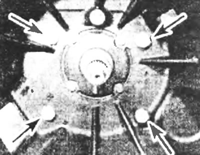
Figure 3.4. Unscrew the bolts (indicated by arrows) and separate the clutch housing from the gearbox housing.
5. Unscrew the bolts and remove the thrust bearing guide sleeve (see figure 3.5). Since the N-type transmission does not have a drain plug, be prepared for some oil to spill when removing the guide bushing.
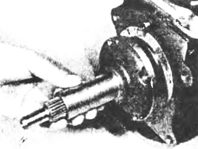
Figure 3.5. Removing the thrust bearing guide sleeve.
6. Using a screwdriver, pry the old oil seal out of the guide bushing. Install the new oil seal using a socket or a piece of pipe of the appropriate diameter to guide it into the recess. Make sure the seal is installed with the seal lip facing towards the transmission housing (see figure 3.6,a,b).
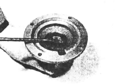
Figure 3.6a. Removing the old oil seal with a screwdriver.
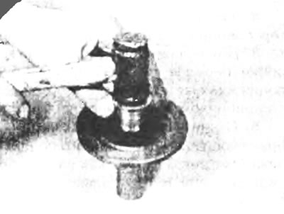
Figure 3.6b. Installing a new oil seal using a large socket or suitable tube.
7. Wipe away all traces of old gasket from the mating surfaces of the guide bushing and the transmission housing.
8. Lubricate the contact lip of the oil seal with multi-purpose grease.
9. Wrap the input shaft grooves with adhesive tape to avoid damaging the oil seal during installation.
10. Using a new gasket, carefully position the guide bushing on the transmission case so that the slot in the gasket and the groove in the guide bushing align with the oil return channel of the transmission case (see Figure 3.10)
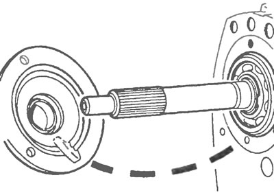
Figure 3.10. Install the clutch thrust bearing guide sleeve onto the gearbox housing so that the gasket cutout and the groove on the guide sleeve align with the gearbox housing lubrication channel.
11. Apply sealant to the guide bushing retaining bolts, install the bolts and tighten them to the specified torque. Remove the protective adhesive tape.
12. Apply a thin layer of high-temperature lubricant to the grooves of the guide sleeve, then install the clutch housing. Install the retaining bolts and tighten them to the specified torque.
13. On the N type transmission, apply a thin coat of high-temperature grease to the release fork shaft, then install the thrust bearing and release fork.
14. Install the gearbox (see Section 7).
MT75 gearbox
Caution: The following procedures require the use of Ford Special Tool #10-040 when removing and installing the input shaft guide bushing. Check for the availability of this tool or a suitable alternative before you begin.
15. Remove the gearbox as described in Section 7.
16. Clean the gearbox thoroughly, paying particular attention to the inside of the clutch housing.
17. After unhooking the thrust bearing from the release fork, remove it from the guide sleeve.
18. After unhooking the release fork from the axle, remove it from the guide sleeve and the input shaft.
19. With a special tool. using a Ford #16-04 or other suitable tool, unscrew the input shaft guide bushing and remove it from the gearbox (see Figure 3.19). Be careful not to lose the thrust washer located behind the guide bushing.
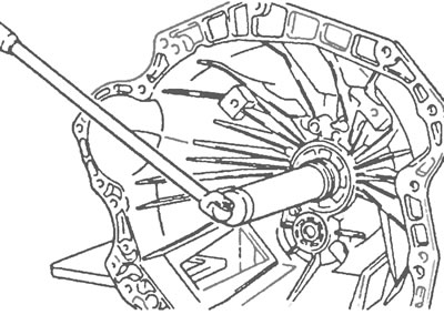
Figure 3.19. Using Ford tool No. 16-040 to unscrew the guide sleeve of the MT75 gearbox input shaft.
20. Using a screwdriver, pry the old oil seal out of the guide bushing. Install a new oil seal using a large socket or a piece of pipe of the appropriate diameter. Make sure the seal is installed with its contact edge facing towards the transmission housing. Also replace the large sealing ring on the edge of the guide bushing with a new one (see Figure 3.20).
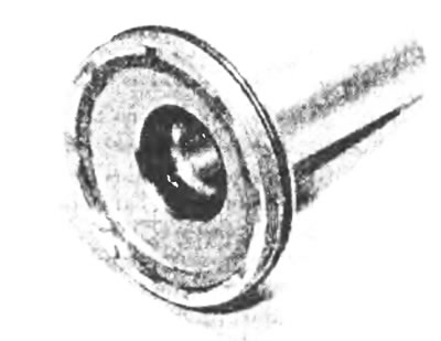
Figure 3.20. MT75 gearbox guide bushing. The oil seal inside the bushing and the large O-ring around the perimeter are clearly visible.
21. Lubricate the oil seal contact lip and O-ring with multi-purpose grease.
22. Wrap the input shaft grooves with adhesive tape to avoid damaging the oil seal during installation.
23. Install the guide bushing and thrust washer and tighten it to the specified tightening torque using the special tool or its alternative.
24. Apply a thin layer of high-temperature lubricant to the grooves of the guide sleeve and the release fork shaft, then install the thrust bearing and release fork.
25. Install the gearbox (see Section 7).
Rear oil seal (driven shaft)
Gearboxes of types G and N
26. With the parking brake applied, jack up the front of the vehicle and place it on supports.
27. On a G type transmission, place a suitable drain pan under the transmission drain plug (see Figure 3.27), unscrew the plug and let the oil drain. Install the plug after the oil has drained completely. Since the N-type transmission does not have a drain plug, be prepared for some oil spillage during the following procedures.
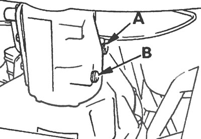
Figure 3.27. Location of filler (A) and drain (B) plugs on a G-type gearbox.
28. Remove the propeller shaft as described in Chapter 8.
29. Using a screwdriver, pry the old oil seal out of its location in the transmission extension. If you cannot remove the seal this way, screw two self-tapping screws into the face of the oil seal at opposite points of the diameter. Then, using pliers, pull first one screw and then the other several times to remove the seal.
30. Clean the groove under the oil seal in the gearbox extension.
31. Dip the new oil seal into clean oil, then press it lightly into the transmission extension to position it perpendicular to the groove walls.
32. Using a socket or a piece of pipe of suitable diameter, carefully insert the oil seal into the groove completely
33. Install the driveshaft as described in Chapter 8. Fill or, if necessary, top up the gearbox oil (see Chapter 1) and lower the car to the ground.
MT75 gearbox
Please note: You will need a new driven shaft flange lock nut and propeller shaft connecting flange bolts during installation.
34. After applying the parking brake, jack up the front of the vehicle and place it on supports.
35. Place a suitable drain pan under the transmission drain plug (see figure 3.35), unscrew the plug and let the oil drain. Install the plug after the oil has drained completely.
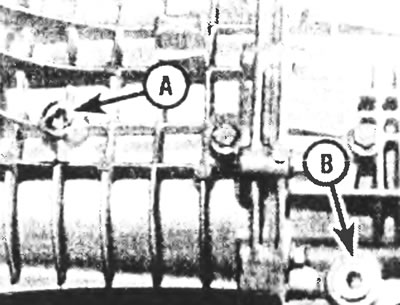
Figure 3.35. Location of filler (A) and drain (B) plugs on the MT75 gearbox.
36. Having marked the relative position of the cardan shaft and the flange of the gearbox driven shaft, unscrew the bolts and separate the cardan shaft from the flange. Set the shaft aside. Please note that new batteries will be required for installation.
37. Holding the driven shaft flange stationary with a rod screwed into one of its holes, unscrew the lock nut (see figure 3.37). Please note that you will need to install a new lock nut during installation.
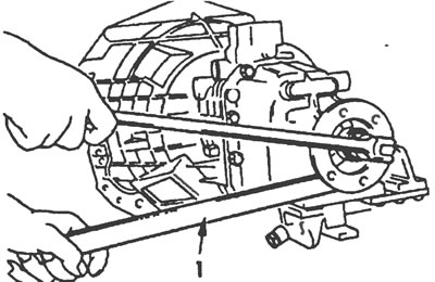
Figure 3.37. Holding the driven shaft flange stationary with a rod screwed to one of its holes, unscrew the lock nut.
38. Remove the driven shaft flange using a two- or three-legged puller (see figure 3.38).
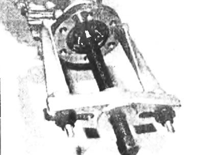
Figure 3.38. Removing the driven shaft flange using a two-legged puller
39. Use a screwdriver to pry the old oil seal out of its location in the transmission housing. If you cannot remove the seal this way, screw two self-tapping screws into the face of the oil seal at opposite points of the diameter. Then, using pliers, pull first one screw and then the other several times to remove the seal.
40. Wipe the groove under the oil seal in the gearbox housing.
41. Dip the new oil seal into clean oil, then press it lightly into the transmission housing to position it perpendicular to the groove walls.
42. Using a socket or a piece of pipe of suitable diameter, carefully insert the oil seal completely into the groove.
43. Lubricate the contact lip of the oil seal and the working surface of the driven shaft flange, then install the flange on the driven shaft.
44. Install the new locknut and tighten it to the specified torque. When tightening the nut, hold the driven shaft flange from rotating in the same way as when removing it.
45. When connecting the propeller shaft, align the marks made during removal. Tighten the new retaining bolts to the specified torque (see Chapter 8).
46. Fill the gearbox with oil in accordance with Chapter 1, then lower the car to the ground.
Oil seal of the driven shaft of the overdrive gear
47. The procedure for replacing the oil seal of the driven shaft of the overdrive transmission is the same as that described above for the seal of the driven shaft on the MT75 gearbox.
Speedometer drive gear oil seal
48. The procedure is described in Section 5.