Withdrawal
All cars
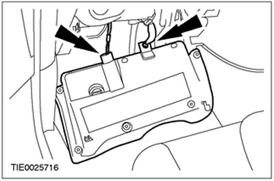
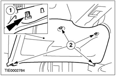
1. Disconnect the bottom section of the instrument panel.
- 1. Remove the screws.
- 2. Release the clip.

2. Remove the bottom section of the instrument panel.
- Disconnect the data link connector (DLC).
- Disconnect the connector for the footwell light (in the presence of).

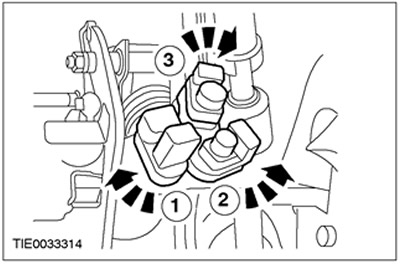
3. Disconnect the plug connectors from the pedal position switches.
- 1.Speed control deactivation switch (in the presence of).
- 2.Stop light switch
- 3. Clutch position switch.
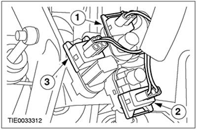
4. Remove the pedal position switches.
- 1.Speed control deactivation switch (Green colour) (in the presence of).
- 2.Stop light switch (gray color).
- 3.Clutch position switch (Red).
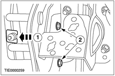
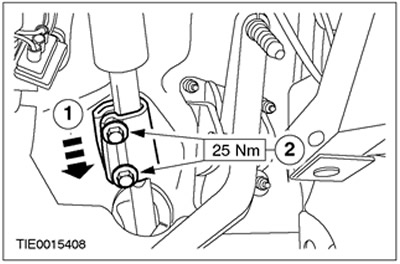
5. Disconnect the clutch master cylinder from the pedal bracket (Clutch position switch bracket shown removed for clarity).
- 1.Remove the clip.
- 2.Remove the bolts.
6. Disconnect the clutch master cylinder drive lever from the clutch pedal.

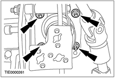
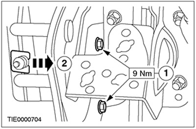
7. Remove the nuts securing the vacuum brake booster (Clutch position switch bracket shown removed for clarity).
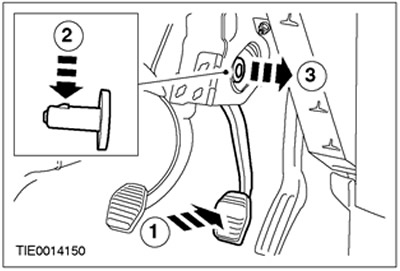
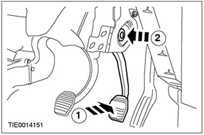
8. Disconnect a pusher of the vacuum amplifier of brakes from a brake pedal.
- 1.Depress the brake pedal.
- 2.Press the clip.
- 3. Remove the brake booster pusher pin and discard it as no longer needed.
Right-hand drive vehicles built up to 12.1998
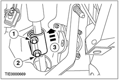
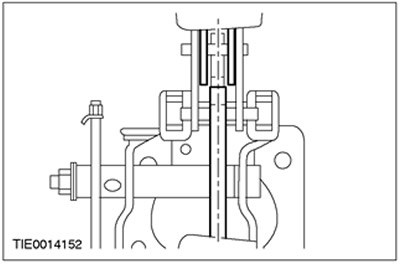
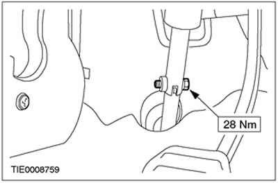
9. Disconnect a shaft of a steering column from the steering mechanism.
- 1. Loosen the top bolt.
- 2. Remove the bottom bolt.
- 3.Move the sleeve up.
Right-hand drive vehicles manufactured from 12.1998
10.
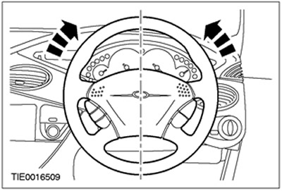
NOTE: Make sure the front wheels are pointing straight ahead.
Set the steering gear to the center position and lock it in this position.
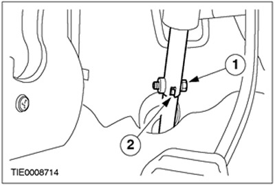
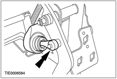
11. Disconnect the steering column shaft from the steering mechanism.
- 1. Remove the bolt and discard it as no longer needed.
- 2. Disconnect the steering gear shaft from the steering column.
Vehicles manufactured since 01.1999
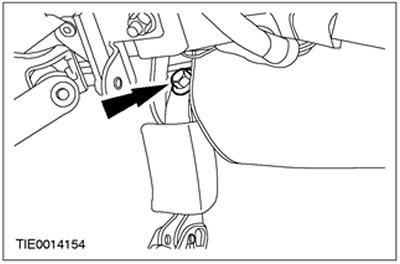
12. Turn out a bolt of fastening of the returnable lever of a pedal of a brake. Remove the air duct if necessary.

All cars
13. Remove the brake pedal bracket.
Installation
All cars
1.
NOTE: Make sure the brake pedal engages with the brake booster push rod.
Install the brake pedal bracket.
2.
NOTE: Do not fully tighten the brake booster mounting nuts at this stage.
Install the brake booster nuts (Clutch position switch bracket shown removed for clarity).

Vehicles manufactured since 01.1999
3.
NOTE: Do not fully tighten the brake pedal return lever mounting bolt at this stage.
Establish a bolt of fastening of the returnable lever of a pedal of a brake.
4.
CAUTION: Make sure there is clearance between the brake pedal and the brake pedal return lever to ensure freedom of movement.
Align the position of the brake pedal return lever and the brake pedal bracket.
All cars
5. Tighten the brake booster nuts (Clutch position switch bracket shown removed for clarity).
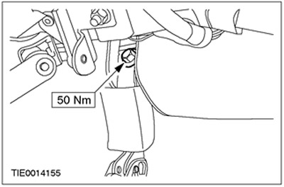
Vehicles manufactured since 01.1999
6. Tighten a bolt of fastening of the returnable lever of a pedal of a brake. Install air duct if necessary.
7. With the engine running, depress the brake pedal three times to make sure the brake pedal moves freely and returns to the unused brake position.
Right-hand drive vehicles built up to 12.1998
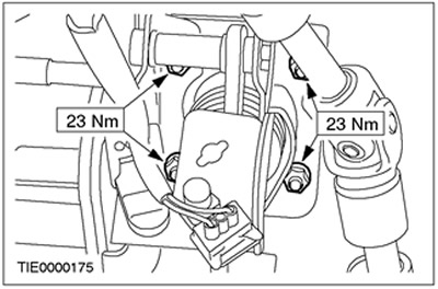
8.
WARNING: Install a new steering column coupler bolt. Failure to follow this instruction may result in injury.
Connect the steering column shaft to the steering gear shaft.
- 1.Move the sleeve down.
- 2.Tighten the bolts.
Right-hand drive vehicles manufactured from 12.1998
9.
WARNING: Install a new steering column coupler bolt. Failure to follow this instruction may result in injury.
Connect the steering column shaft to the steering gear shaft.
All cars
10. Connect the clutch master cylinder drive lever to the clutch pedal.
11.
NOTE: Insert the clutch master cylinder into the holes in the pedal support bracket.
Connect the clutch master cylinder to the pedal bracket (Clutch position switch bracket shown removed for clarity).
- 1.Install the bolts.
- 2.Install the clip.
12.
CAUTION: Install a new brake booster pushrod pin.
Establish a pin of a pusher of the vacuum amplifier of brakes.
- 1.Depress the brake pedal.
- 2.Install the brake booster push pin.
13.
NOTE: Clutch position switch (Red) not regulated.
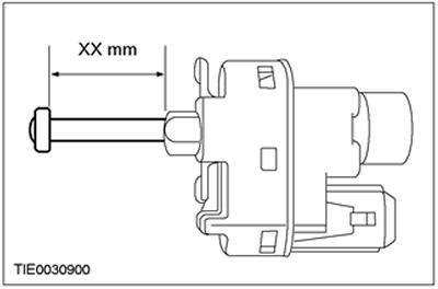
Fully extend the speed control deactivation switch plungers (in the presence of) and stoplight switch.
- Measure the plunger length.
- Speed control deactivation switch (Green colour) XX mm = 24 mm.
- Stoplight switch (gray color) XX mm = 21 mm.
14.
CAUTION: When installing the switches, turn the brake light switch counterclockwise and the other switches clockwise. Failure to follow this instruction will result in sticking of the plungers.
CAUTION: Make sure the switches are set correctly.
NOTE: Speed Control Disable Switch (in the presence of) and brake light switch are automatically adjusted during installation.
NOTE: Slight noise and clicking sensation during speed control deactivation switch setting (in the presence of) and the brake light switch is normal.
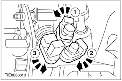
Install the pedal position switches.
- 1.Clutch position switch (Red).
- 2.Stop light switch (gray color).
- 3.Speed control deactivation switch (Green colour) (in the presence of).
15.
NOTE: The colors of the plugs and switches are identical.
Connect the plug connectors of the pedal switches.
- 1.Speed control deactivation switch (in the presence of).
- 2.Stop light switch
- 3. Clutch position switch.

16. Connect the data link plug (DLC) and connectors for footwell lighting (in the presence of).
17. Establish the lower section of the panel of devices.
- 1.Fix the clip.
- 2.Install the screws.
Visitor comments