2. On later models, the thermostatic sensor is part of the fuel pump and is not replaceable.
Removal
3. Disconnect the negative battery cable.
4. Drain the cooling system as described in Chapter 1.
5. Unscrew the two bolts securing the thermostatic sensor to the thermostat housing. Remove the sensor and gasket from the housing (see Figure 5.5), please note that reassembly requires the installation of a new gasket.
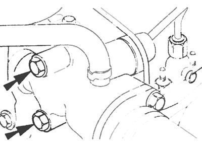
Figure 5.5. Thermostatic sensor fixing bolts.
6. Unscrew the outer cable locknuts from the support bracket on the fuel pump.
7. Disconnect the end of the inner cable from the idle speed control lever. On the Bosch high pressure fuel pump, the inner cable is released by loosening the screw that attaches the cable to the spring fixture at the end.
8. Remove the thermostatic sensor and cable.
9. Completely clean all traces of the old gasket from the thermostat housing and sensor mating surfaces, and place the new gasket in position(s).
10. Install the sensor and secure it with the fixing bolts.
11. Install the cable in the reverse order of removal, but the cable lock nuts (and the spring clamp screw on Bosch pumps) leave loose all the way for adjustment.
12. Adjust the cable as described below, then fill the cooling system (see Chapter 1) and connect the battery.
Regulation
13. Move the speed control lever to the extreme position corresponding to maximum speed and temporarily secure it in this position.
14. On the Bosch feed pump, pull back the spring end of the cable connected to the idle speed control bracket and tighten the screw to secure the inner cable (see Figure 5.14, a, b).
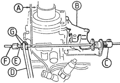
Figure 5.14a. Adjusting the idle speed on the Bosch fuel pump: A - Gap 2-3 mm, B - Idle speed control lever, C - Tensioner, D - Bracket, E - Adjustment thread, F - Cable sheath, G - Lock nuts.
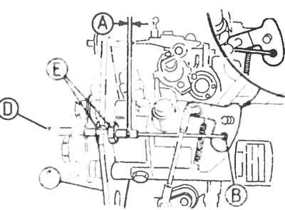
Figure 5.14b. Adjusting the idle acceleration on the Lucas/CAV fuel pump: A - Gap 2-3 mm, B - Idle speed control lever, C - Bracket, D - Cable sheath, E - Lock nuts
15. Adjust the position of the lock nuts so that there is a gap of 2-3 mm between the edge of the outer sheath and the end nipple of the cable. Tighten the locknuts.
Installation
16. Pull the outer sheath of the cable towards the rear of the engine until the cable is taut (for Bosch pump) check that the clamping sleeve at the end of the cable compresses the springs to the stop, and for a Lucas/CAV pump, check that the speed control lever is pressed against the cold start stop. In this case, the gap between the sheath and the end nipple of the cable should remain within 2-3 mm.
17. Disconnect the idle speed control lever.