Contents: Examination ↳ Regulation ↳
Note: The setting pins described in the previous section will be needed for subsequent checking and adjustment. Do not attempt to rotate the engine with any of the dowel pins installed, and do not use the dowel pins as a means of preventing the engine from rotating when loosening or tightening the lock nuts or bolts.
Examination
1. Disconnect the negative battery cable.
2. Remove the plug from the timing belt cover and the rubber plug from the crankshaft pulley (see figure 9.2,a,b).
3. Remove the plastic plug from the hole for the crankshaft lock at the rear of the engine, just above the starter. On turbocharged engines with the Lucas EPIC system, the crankshaft position and speed sensor is located above the crankshaft locking pin hole. Disconnect the multi-pin plug, unscrew the retaining bolt, and remove the sensor. Remove the gasket behind the sensor if installed.
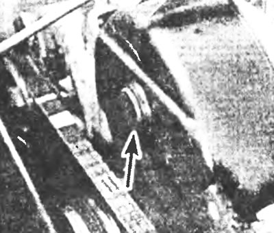
Figure 9.2a. Remove the plug from the timing belt cover.
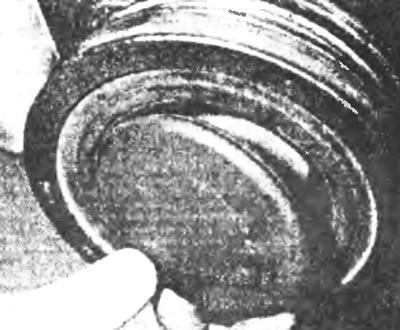
Figure 9.2b.... and the rubber plug of the crankshaft pulley.
4. Turn the crankshaft pulley using a wrench until the U-shaped cut in the fuel pump sprocket is visible through the hole in the timing belt cover. Perhaps. You'll need a mirror to accurately observe the movement of the toothed pulley through the cover opening.
5. Insert the crankshaft locking tool into the hole for it at the rear of the engine with light pressure and slowly turn the crankshaft pulley back and forth until the locking tool enters the hole in the flywheel (see Figure 9.5).
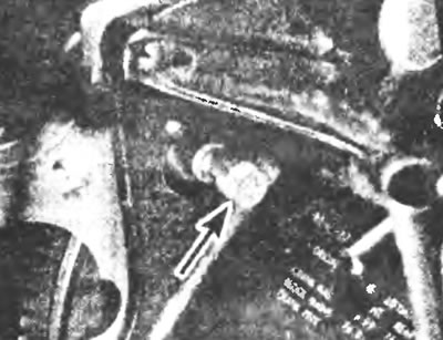
Figure 9.5. Insert the crankshaft locking tool into the crankshaft locking tool hole at the rear of the engine.
6. After inserting the crankshaft lock, try to insert the fuel pump lock through the U-shaped cut into the hole behind it (see Figure 9.6). If the retainer goes in easily, the fuel injection advance is adjusted correctly. Remove the clamps, install all plugs and covers, connect the battery. On engines with a crankshaft angle sensor, install the sensor and clearance shim, if equipped.
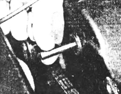
Figure 9.6 Insert the fuel pump retainer through the U-shaped cut into the hole behind it.
7. If the retainer does not fit into the hole, the fuel injection advance must be adjusted as follows.
Regulation
8. Contact Chapter 2A and remove the timing belt cover.
9. Insert the crankshaft locking tool into the hole as described above.
10. Lock the camshaft timing pulley by inserting the camshaft locking tool through the hole in the timing pulley behind it (see Figure 9.10).
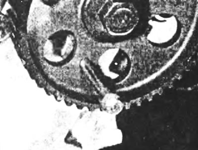
Figure 9.10. Lock the camshaft timing pulley by inserting the locking pin through the hole in the timing pulley into the hole behind it.
11. Loosen the fuel pump sprocket retaining bolts and gently tap one of the loose bolts with a mallet in one direction and then the other until the retainer is fully inserted. Once the retainer is installed, tighten the fuel pump sprocket retaining bolts.
12. If the movement of the grooves of the fuel pump toothed pulley does not allow the retainer to be installed, then it is necessary to remove the toothed drive belt and repeat the procedure. Refer to Chapter 2A, section 7 for removing, installing and tensioning the toothed drive belt.
13. After completing all work, remove the fasteners and install all removed components in their places, referring to the relevant Chapters for information.
For more information, please visit the specified website FORDBOOK