2. Insert the top compression ring into the first cylinder and position it perpendicular to the cylinder walls, pushing it inward with the top of the piston.
3. To measure the cut gap, slide the blades of the feeler gauge between the ends of the ring until the thickness of the blade is equal to the width of the gap (see Figure 20.3). The feeler gauge should slide between the ends of the ring with slight resistance. Compare the measured values with the values given in the specifications. If the gap exceeds or falls outside the allowable limits, recheck to ensure that the correct ring was used during the measurement process. If you decide to evaluate the condition of your existing rings, have your Ford dealer or similar engine repair specialist accurately measure the cylinder bore so you can confirm exactly which component is worn and get advice on how to proceed.
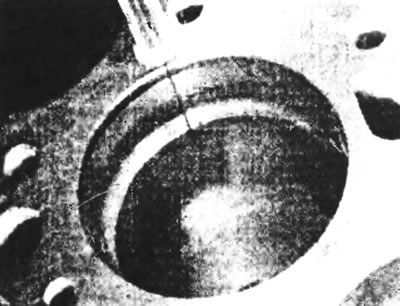
Figure 20.3. Measure the gap in the piston ring joint with a feeler gauge.
4. If the cut gap is still too small, it can be carefully widened with a fine file. Excessive clearance in the ring lock is not a problem as long as it does not exceed the specification limit, otherwise a very careful check of the dimensions of all components as well as new parts is required.
5. Repeat the procedure with the remaining rings of the 1st cylinder and for the rings of the remaining cylinders.
6. Install the piston rings as described below. When installing the original rings, use the marks or notes made during removal to ensure that each ring is installed in the same groove and with the same side facing up. New rings will usually have a mark on the top surface (often the mark is the ring size, such as "STD", or the word "TOP").
Caution: Always follow the instructions printed on the ring packaging - different manufacturers may require different approaches. Do not confuse the top and second compression rings, as they usually have different cross-sections.
7. Oil scraper ring (lower on the piston) is usually installed first. It consists of three separate components. Insert the spring and expander into the groove. If there is a protrusion on the ring, make sure that it fits into the drilled hole in the groove. Then install the bottom eraser edge. When installing scraper lips, do not use a ring installation tool as they may be damaged. To install correctly, insert one end of the wiper edge into the groove between the spring and expander and the bottom wall of the groove, and while holding it in place, run your finger around the circumference of the piston, gently pressing the wiper edge into the groove. Then install the top erasing edge in the same way.
8. After all three components of the oil control ring are installed, ensure that both the upper and lower wiper edges rotate smoothly in the groove.
9. Next, install the second compression (middle) ring, followed by the top compression ring - make sure their marks are facing up and be careful not to confuse them. Do not expand the ring more than necessary to fit it onto the piston.
10. After installing the rings, measure the gap between the ring and the groove using a feeler gauge and make sure it is within specification (see figure 20.10).
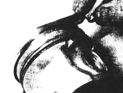
Figure 20.10. Measure the gap between the piston ring and the groove.
11. After setting the clearances, place the rings so that the cuts on the compression rings are at opposite points on the piston in line with the piston pin, and the cuts on the oil scraper ring are on a perpendicular line passing through the center of the piston skirt.