Please note: New bolts will be required when installing the crankshaft main bearing caps.
1. Both the cylinder block and crankshaft must be cleaned, inspected and reconditioned or repaired as necessary. Place the engine upside down.
2. Unscrew the bolts and remove the covers. Set the covers aside in the order they are installed on the engine.
3. If the old bearing shells are still in place, separate them from the block and main bearing caps. Wipe the bearing beds on the block and in the caps with a clean, lint-free cloth. They must be absolutely clean!
Checking the main bearing clearance
Remember: To check the main bearing clearance, you will need Plasigage plain bearing clearance testing material, available from Ford dealers.
4. Wipe the back walls of the new bearing shells and place the shells one by one in the "bed" (recesses for the liner) in the main bearing caps of the block. Insert the corresponding upper liners (dry) into the crankshaft housing "beds". When installing old main bearings, make sure they are installed in their original locations. Make sure that the protrusion on the bearing shell fits into the recess in the cylinder block or cover (see Figure 21.4).
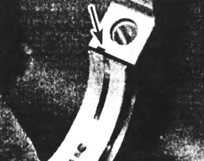
Figure 21.4. Make sure that the protrusion of each bearing fits into the corresponding groove in the cylinder block or cover.
Caution: Do not hammer the bearings into their seats, and be careful not to damage their anti-friction alloy coated faces. No lubricant should be used at this stage.
5. Place the crankshaft thrust washers in the crankcase so that their oil grooves face outward (away from the central cheek) (see Figure 21.5).
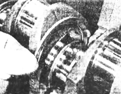
Figure 21.5. Install the crankshaft thrust washers in place so that their oil grooves face outward.
6. Clean the working surfaces of the block bearings and the crankshaft main journals with a clean, lint-free soft cloth. Clean the crankshaft oil holes, as any dirt here can only find one way out - directly into the new bearings.
7. Once you are sure the crankshaft is clean, carefully place it back into the main bearings. Cut several pieces of the appropriate length from the hair "Plastigage" (they should be slightly shorter than the width of the main bearings) and place one hair on each main journal of the crankshaft parallel to its axis (see Figure 21.7).
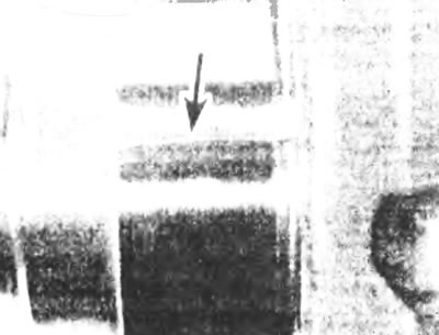
Figure 21.7. Place a strip of "Plasigage" on the main bearing journal parallel to the crankshaft axis.
8. Clean the bearing surfaces in the caps and install the caps in their places (don't confuse them) so that the arrows point forward along the engine. Do not move the hair of the plastic measuring tool. Use the old bolts, saving the new ones for final installation.
9. Starting from the center main bearing and working toward the end of the engine, tighten the main bearing cap bolts in three stages to the specified torque, according to Specifications. Do not turn the crankshaft and ensure that all covers are installed strictly perpendicular to the cylinder block.
10. Remove the bolts and carefully lift the main bearing caps. Be careful not to damage the hair "Plastigage" and do not turn the crankshaft. If any of the lids are difficult to remove, lightly tap them on the sides with a soft-faced mallet.
11. Measure the width of the crushed thread of the plastic measuring tape on each neck using the special scale printed on the packaging "Plastigage" (see figure 21.11). Compare the obtained values with the values given in the specifications.
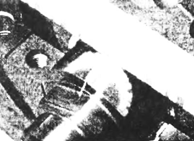
Figure 21.11. Compare the width of the crushed hair with the stripes on the special scale to determine the gap. Take the measurement at the widest point of the hair. Remember that there are two scales: metric and inch - do not confuse them.
12. If the clearance is not within specifications, consult your Ford dealer or engine repair specialist - if the crankshaft journals are in good condition, the bearings may be the wrong size (it may be necessary to install different sized bearing shells in the same bearing to achieve the correct clearance). If this is not possible, the crankshaft must be turned in a car service workshop. However, before making a decision, make sure that no dirt or oil got under the liner when you took the measurement. If the crushed hair of a plastic gauge is wider on one side than on the other, then there is a taper of the neck (see Section 17).
13. Carefully erase all traces "Piastigage" from all main journals and working surfaces of the bearing. Be very careful not to scratch the anti-friction layer of the bearing - remove "Plastigage" with a fingernail or the corner of a credit card.
Final installation of the crankshaft
14. Carefully remove the crankshaft from the engine. Clean the working surfaces of the bearings in the block and then lubricate them with a thin, even layer of clean motor oil (see Figure 21.14). Also lubricate the working surfaces of the thrust washer.
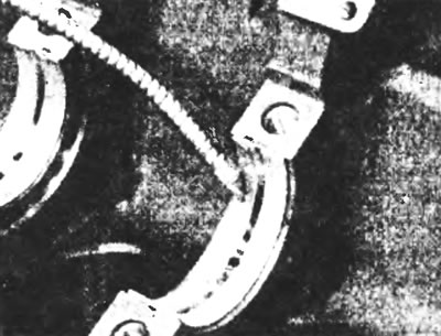
Figure 21.14. Apply a small amount of clean engine oil to the working surface of each bearing.
15. Make sure the crankshaft journals are clean and reinstall the crankshaft into the cylinder block. Clean the working surfaces of the liners in the lids, then lubricate them. Install the covers in their places so that the arrows point towards the timing belt.
16. Working one cap at a time, starting at the center main bearing and working toward the end of the engine, tighten the main bearing cap retaining bolts in three stages to Specifications. In this case, do not turn the crankshaft and make sure that the covers are installed without distortions, perpendicular to the cylinder block.
17. Turn the crankshaft by hand several times to ensure that there are no binding points during rotation.
18. Finally, check the crankshaft longitudinal play using a feeler gauge or dial gauge (see Section 14). If the crankshaft thrust surfaces are not worn or damaged, and new bearings are installed, the longitudinal clearance should be within the permissible limits.