2. Remove the cover from the lower head of the 1st connecting rod (in accordance with the identification marks placed upon removal). Remove the originally installed bearing shells and wipe the connecting rod and cap mating surfaces with a clean, lint-free cloth.
Remember: all contact surfaces must be absolutely clean!
Checking the clearance in the connecting rod lower head bearings
Remember: To check the main bearing clearance, you will need Plastigage plain bearing clearance testing material, available from your Ford dealer.
3. Clean the back surface of the bearing shell and place it in the connecting rod, then install the other shell of the same bearing in the connecting rod cap. Make sure the tab on each bearing fits into the groove in the cap or connecting rod.
Caution: Do not hammer the bearing shells into their seats, and be careful not to damage their anti-friction alloy coated faces. No lubricant should be used at this stage.
4. It is extremely important that all contact surfaces of the supporting elements are completely clean and free of oil during assembly.
5. After setting the piston ring gaps as described in Section 20, lubricate the piston and rings with clean engine oil and install the piston ring compressor onto the piston. With the piston skirt extended about a quarter inch from the tool, guide the piston into the cylinder. The rings must be compressed until they enter the cylinder together with the piston.
6. Turn the crankshaft so that the connecting rod journal of the 1st cylinder is at the bottom dead center (BDC) position, then lubricate the cylinder walls with clean engine oil.
7. Then, with the piston positioned as noted during removal, gently insert the assembly into No. 1 inside diameter of the cylinder, and rest the bottom edge of the piston ring compressor against the engine block.
8. Tap the top edge of the piston ring compressor until its bottom edge is pressed against the engine block along its entire length.
9. Gently tap the bottom of the piston with a wooden hammer handle (see Figure 22.9), insert the piston into the cylinder, while directing the lower head of the connecting rod towards the crank pin. Piston rings can break at the transition before entering the cylinder bore, so keep the piston ring compressor pressed against the cylinder block surface at all times. Work slowly and if you experience the slightest resistance to the piston entering the cylinder, stop immediately. Find out the cause of the resistance and eliminate it before proceeding. Never, for any reason, force the piston into the cylinder - you may break the ring or the piston.
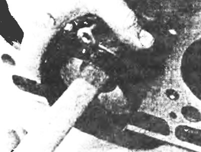
Figure 22.9. Lightly tapping the bottom of the piston with the wooden handle of a hammer, insert the piston into the cylinder so that the connecting rod rests on the journal.
10. To check the big-end bearing clearance, cut a piece of Plastigage to the appropriate length (slightly shorter than the crankpin width) and place it on the crankpin of the first cylinder parallel to the crankshaft axis (see Figure 21.7.)
11. Clean the mating surfaces of the connecting rod and cap and install the connecting rod small end cap. Tighten the union nuts evenly in two stages to the specified torque. Do not rotate the crankshaft during this procedure.
12. Unscrew the nuts and remove the cover - be extremely careful not to damage the hair "Plastigage".
13. Measure the width of the crushed thread "Plastigage" using the scale printed on the gauge packaging to obtain the working clearance (see figure 21.11). By comparing the gap with the values given in the specifications, ensure that the gap is within the acceptable limits.
14. If the clearance is not within the specified limits, consult your Ford dealer or engine repair specialist - if the crankshaft journals are in good condition, the bearing shells may simply need to be replaced with new ones to achieve the correct clearance. If this is not possible, the crankshaft must be reground by a specialist and fitted with the necessary oversize liners. However, first check that no dirt or oil got under the bearings when the clearance was measured. Also recheck the diameter of the corresponding neck. If the crushed thread of the plastic measuring tool is wider at one end than at the other, this indicates the presence of a taper in the neck (see Section 17).
15. Carefully clean all traces of plain bearing clearance measuring material from the bearing journals and running surfaces. Be very careful not to scratch the anti-friction layer of the bearing - remove "Plastigage" with a fingernail or the corner of a credit card.
Final installation of the connecting rod and piston group
16. Make sure the bearing surfaces are absolutely clean, then lubricate both shells evenly with clean molybdenum grease, engine assembly grease, or, as a last resort, clean engine oil. To gain access to the working surface of the bearing, you will need to slightly push the bearing shell out of the connecting rod, moving the connecting rod to the side along the crank journal.
17. After returning the bearing shell to its place, install the connecting rod cap, and then tighten the nuts as described above (see Figure 22.17).
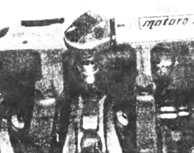
Figure 22.17. Tighten the connecting rod cap nuts to the specified tightening torque.
18. Repeat all procedures for the remaining groups.
19. Once all connecting rod and piston assemblies are installed, check the clearance between the top of each piston and the face of the cylinder block using a dial gauge (see Figure 22.19). Set the gauge to zero on the face of the block, then lift each piston one at a time to TDC. Place the gauge needle on the top of the piston and check the clearance using the arrow on the scale. If the protrusion of any piston is not within Specifications, replace the connecting rod of that piston with a connecting rod of longer or shorter length. The cranks are available in four lengths, identified as 1A, 2A, 3A and 4A: 1A is the shortest, 4A is the longest.
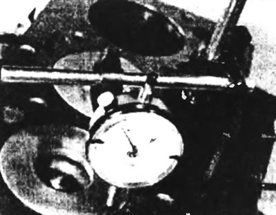
Figure 22.19. Check the clearance between the top of each piston and the top surface of the cylinder block using a dial gauge.
20. Finally, when all the connecting rod and piston group parts are properly installed, turn the crankshaft by hand several times and make sure that the shaft does not jam during rotation.
[The text is available on the specified website info portal FordBook.ru]