In the R4 16V Duratec Ti-VCT engine, the marks on the VCT mechanisms, made together with the toothed pulleys of the camshafts, serve only for preliminary approximate installation of the crankshaft and camshafts in the required position. For precise installation of the piston of the 1st cylinder in the TDC position of the compression stroke, two special devices are required to fix the crankshaft and camshafts in a certain position.
You will need: special devices for fixing the crankshaft and camshafts, a 10 mm socket wrench, 8 mm and 13 mm open-end wrenches or socket heads, and an 18 mm wrench.
1. Remove the air conditioning compressor drive belt (see "Replacing the Air Conditioning Compressor Drive Belt") and the accessory drive belt (see "Replacing the accessory drive belt").
2. Remove the generator (see "Removing and installing the generator").
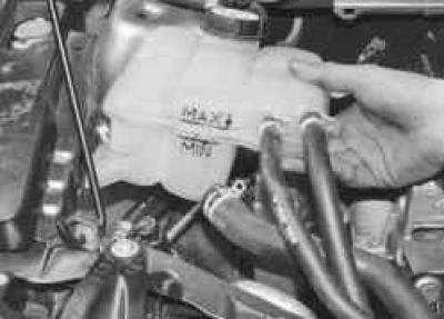
3. Remove the expansion tank from the brackets on the body and move it to the side without disconnecting the hoses.
4. Place a secure support under the engine.

5. Remove the right front support of the power unit suspension by unscrewing the two nuts securing it to the bracket on the engine and unscrewing the two bolts securing it to the mudguard of the engine compartment.
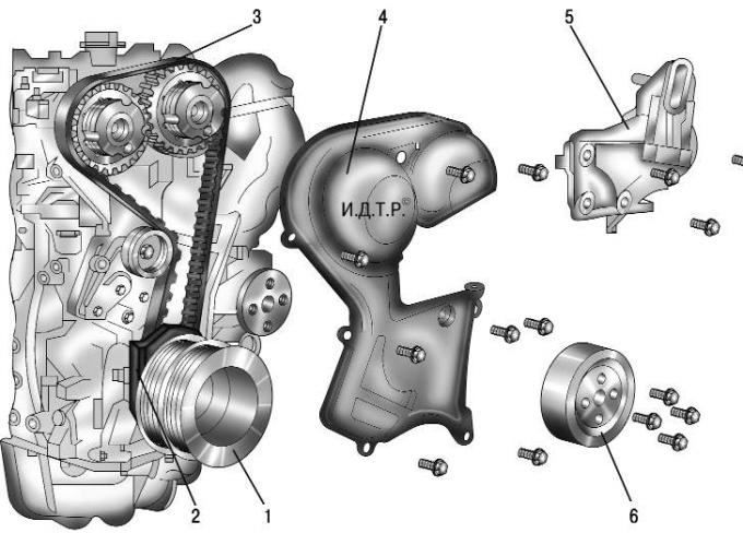
Fig. 4.13. Engine components removed when replacing the timing belt: 1 – crankshaft pulley; 2-lower cover of the timing belt; 3 – timing belt of the gas distribution mechanism; 4 - front cover of the timing belt; 5 – bracket of the right support of the power unit suspension; 6 – water pump pulley
6. Remove pulley 6 (see Fig. 4.13) of the water pump by unscrewing the four bolts that secure it.
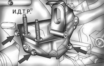
Fig. 4.14. Fastening the bracket of the right support of the power unit suspension
7. Remove the bracket (see Fig. 4.14) of the right support of the power unit suspension by unscrewing the three bolts that secure it.
8. Remove the front cover 4 (see Fig. 4.13) of the timing belt by unscrewing the eight bolts that secure it.
9. Shift the transmission into neutral.
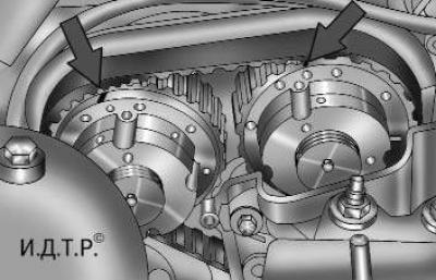
Fig. 4.15. Setting marks on VCT mechanisms
10. Turn the engine crankshaft by the bolt securing its pulley so that the marks on the VCT (variable valve timing) mechanisms of the camshafts are positioned as shown in Fig. 4.15 ("at eleven o"clock").
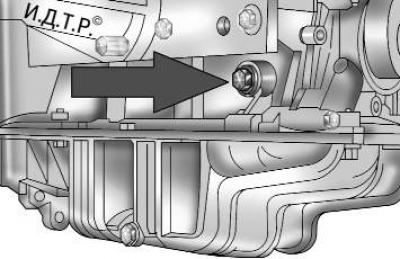
Fig. 4.16. Plug for the hole for installing the crankshaft locking rod
11. Unscrew the plug located in the front part of the cylinder block on the right (see Fig. 4.16) and install the locking rod into the opened hole until it stops against the crankshaft. Carefully turn the crankshaft by the bolt securing its pulley until the shaft stops with the locking rod.
NOTE: The locking rod is a cylindrical part approximately 65 mm long (stepped in diameter). The 10 mm long part of the rod with a small diameter (4 mm) is a shank that fits into the groove of the crankshaft. The remaining cylindrical part with a larger diameter (8 mm) serves as a guide in the cylinder block bore.
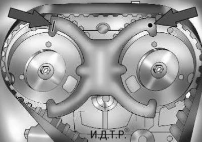
Fig. 4.17. Fixing the camshafts from turning with a special device
12. Install the locking device in the special grooves in the VCT mechanism housings (see Fig. 4.17). Install the device so that the marks on its branches are at the top, with the line-shaped mark on the exhaust camshaft side and the dot-shaped mark on the intake camshaft side. If the device can be installed without difficulty, the timing belt is installed correctly, the piston of the 1st cylinder is at TDC of the compression stroke and the initial setting of the valve timing corresponds to the norm. If the device cannot be installed (the valve timing is shifted), remove the timing belt, install the locking device and put the belt on correctly (see "Replacing the timing belt").
13. Install the removed parts in the reverse order of removal.