To accurately set the piston of the 1st cylinder to the TDC position of the compression stroke, two special devices are required to fix the crankshaft and camshafts in a certain position.
You will need: special devices for fixing the crankshaft and camshafts, a 10 mm socket wrench, 8 mm and 13 mm open-end wrenches or socket heads, and an 18 mm wrench.
1. Disconnect the wire from the negative terminal of the battery.
2. Remove the decorative engine cover (see Removing and installing the decorative engine cover).
3. Remove the cylinder head cover (see Replacing the cylinder head cover gasket).
4. Remove the right front wheel.
5. Remove the engine splash guard (see Removing and installing mudguard and engine crankcase protection).
6. Remove the right front fender liner (see Removing and installing wheel mudguards and fender liners).
7. Shift the transmission into neutral.
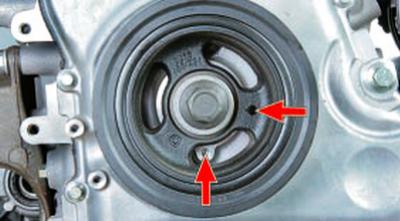
8. Turn the engine crankshaft by the bolt securing its pulley so that the hole in the crankshaft pulley is approximately 45° short of the threaded hole in the timing cover, and the cams of the valves of the 1st cylinder are directed upward.
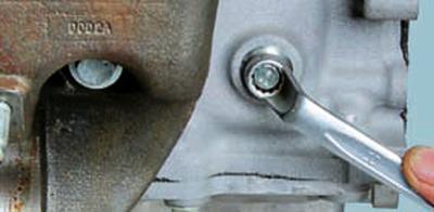
9. Loosen the tightening…
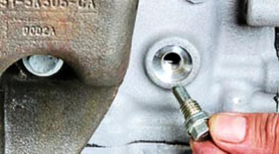
10….and remove the plug located at the front of the cylinder block on the right.
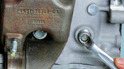
11. Screw in the locking rod (device M10x1.5).
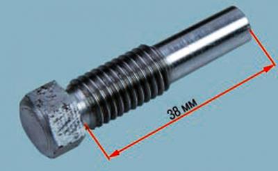
NOTE: This is what the M10x1.5 device looks like for setting the crankshaft to the TDC position of the compression stroke.
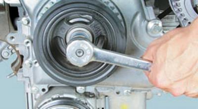
12. Carefully turn the crankshaft by the bolt securing its pulley until the shaft stops with the locking rod.
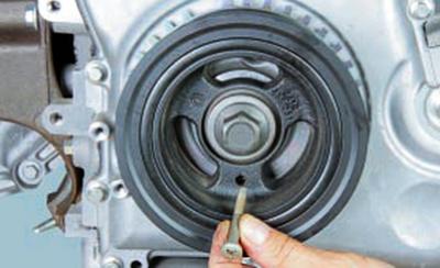
13. On 2.0 and 2.3 L Duratec-HE engines, screw the M6x18 bolt through the hole in the crankshaft pulley into the threaded hole in the timing cover, thereby securing the crankshaft from turning.
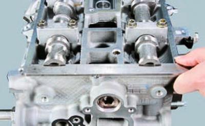
14. Install the retaining plate into the special grooves at the rear of the camshafts.
15. On the 1.6L Duratec Ti-VCT engine, install the tool so that the marks on its branches are at the top, with the line mark on the exhaust side and the dot mark on the intake side.
If the device was installed without difficulty, the piston of the 1st cylinder is at TDC of the compression stroke and the initial setting of the valve timing corresponds to the norm.
If the device could not be installed (the valve timing is shifted), remove the timing belt, install the locking device and put the belt on correctly (see Checking and replacing the timing belt of the 1.6L Duratec Ti-VCT engine) or chain (see Replacing the timing chain of the 2.0 and 2.3 L Duratec-HE engines) timing drive depending on the engine type.
16. Install the removed parts in the reverse order of removal.
(The material was copied from an information website www.fordbook.ru)