- the pressure in the engine lubrication system has dropped. The cause of this malfunction is often increased wear of the camshaft journals and camshaft bearing beds in the cylinder head. If the beds and their covers are worn out, the cylinder head is replaced as an assembly, since the beds are made directly in its body;
- valve knocking with normal clearances in the valve drive mechanism. Caused by increased wear of the camshaft cams due to the use of low-quality motor oil or damage to the oil filter.
You will need: the same tools as for removing the timing belt (see "Replacing the timing belt"), camshaft seals (see "Replacing camshaft seals"), as well as a TORX E11 key, a torque wrench.
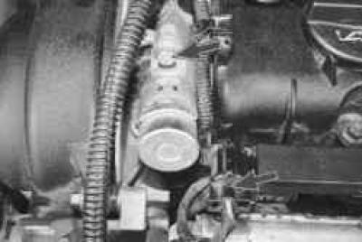
1. Remove the VCT solenoid valves by disconnecting the wiring harness connectors from them and unscrewing one bolt each that secures them to the VCT caliper.
2. Remove the cylinder head cover (see "Replacing the cylinder head cover gasket").
3. Remove the timing belt (see "Replacing the timing belt").
4. Remove the VCT mechanisms (see "Replacing camshaft seals").
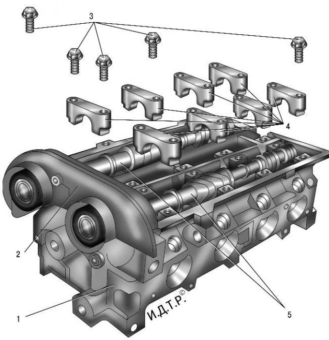
Fig. 5.14. Removing the camshafts: 1 – cylinder head; 2 – VCT support; 3 – camshaft bearing cap mounting bolts; 4 – camshaft bearing caps; 5 – camshafts
5. Remove the VCT caliper (item 2 in Fig. 5.14) by unscrewing the four bolts securing it to the cylinder head.
NOTE: The VCT caliper mounting bolts are different lengths: those located further from the longitudinal axis of the cylinder head are 38 mm, those closer to the axis are 51 mm. Do not mix them up when reinstalling.
6. Unscrew bolts 3 (see Fig. 5.14) securing the camshaft bearing caps 4 in the reverse order shown in Fig. 5.15, and remove the camshafts.
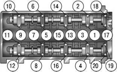
Fig. 5.15. Tightening order of camshaft bearing cap bolts
WARNING: The camshaft bearing caps are marked with their serial numbers. Remember or write down the location of the caps in order to install them in their original places: the caps are processed together with the cylinder head and it is prohibited to depersonalize them.
7. Remove the oil seals from the camshaft journals.
NOTE: Note
NOTE: Replace the camshaft seals with new ones each time they are removed.
8. Inspect the camshafts. There should be no damage or wear on the threads in the holes for mounting the VCT mechanism. The surfaces of the bearing journals and cams should be well polished and without damage. No scoring, nicks, scratches, or aluminum drag from the bearing seats in the cylinder head are allowed on the working surfaces of the journals. If traces of seizure, overheating, deep scratches, or faceted wear are found on the working surfaces of the cams, replace the shafts.
WARNING: Grinding the camshaft lobes to eliminate stepped wear is prohibited, as changing the cam profile dimensions will disrupt the valve timing.
9. In workshops equipped with special tools and devices, you can check the radial runout of the camshaft journals. If the runout is more than 0.02 mm or the journals are not aligned, replace the shaft, since its straightening is not allowed.
10. Lubricate the camshaft beds with clean engine oil and place the camshafts in them in such a position that none of the cams rests with the highest part of its nose on the valve tappet adjusting washer.
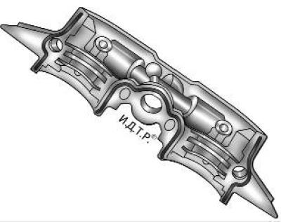
Fig. 5.16. Places to apply sealant to the VCT caliper
11. Install the VCT caliper, having first applied sealant to its surfaces, as shown in Fig. 5.16.
12. Install the camshaft bearing caps, tighten their mounting bolts and the VCT caliper mounting bolts in the order shown in Fig. 5.15, in three stages:
- Step 1 - Tighten the bolts evenly, 1/2 turn each, until the bearing caps and VCT caliper contact the cylinder head surfaces;
- Step 2 - Tighten the camshaft and VCT caliper bearing cap bolts to 7 Nm;
- Step 3: Tighten the camshaft and VCT caliper bearing cap bolts by 45°.
13. Press the camshaft seals into the VCT caliper sockets (see "Replacing camshaft seals").
14. Install the remaining removed parts in the reverse order of removal.
[The original article can be viewed on the portal: Fordbook.ru]