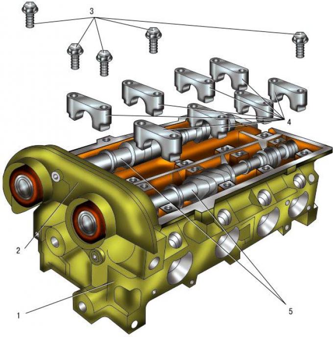
Pic. 5.36. Removing the camshafts of the Duratec Ti-VCT engine with a volume of 1.6 liters: 1 - cylinder head; 2 – support VCT; 3 – bolts of fastening of covers of bearings of camshafts; 4 – covers of bearings of camshafts; 5 - camshafts.
Camshafts are replaced in the following cases: - The pressure in the engine lubrication system has dropped. The cause of this malfunction is often increased wear on the camshaft journals and camshaft bearing beds in the cylinder head.
When the beds and their covers are worn out, the block head is replaced as an assembly, since the beds are made directly in its body; - valve knock at normal clearances in the valve drive mechanism. Caused by increased wear of the camshaft cams due to the use of low-quality engine oil or damage to the oil filter.
To replace the 1.6L Duratec Ti-VCT engine camshafts, follow these steps.
You will need: the same tools as for removing the timing belt and camshaft oil seals, as well as a TORX E11 wrench, a torque wrench.
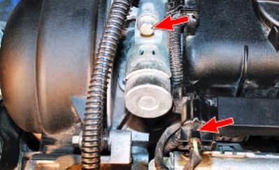
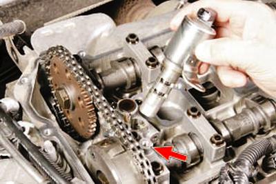
1. Remove the solenoid valves of the VCT system by disconnecting the wiring harness blocks from them and unscrewing one bolt securing the VCT system caliper.
2. Remove the cylinder head cover (refer to Cylinder Head Cover Gasket Replacement).
3. Remove the timing belt (refer to Inspection and replacement of the timing belt for the 1.6L duratec ti-vct engine).
4. Remove VCT mechanisms (see Replacing camshaft seals) and VCT caliper (pos. 2 in fig. 5.36), having unscrewed four bolts of its fastening to a head of the block of cylinders.
NOTE: VCT caliper mounting bolts of different lengths: located further from the longitudinal axis of the block head - 38 mm, closer to the axis - 51 mm.
NOTE: Do not mix them up when reinstalling.
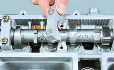
5. Remove covers 4 of bearings of camshafts, having turned out bolts 3 of their fastening.
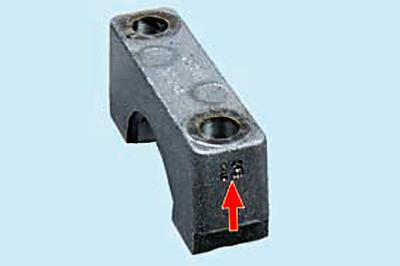
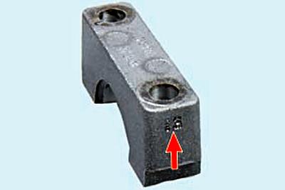
WARNING: Camshaft bearing caps are marked with serial numbers.
WARNING: Remember or write down the location of the covers in order to install them in their original places: the covers are processed together with the cylinder head and it is forbidden to depersonalize them.
WARNING: When installing, keep in mind that the marks are on the outside of the covers.
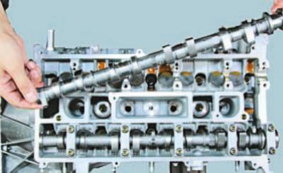
6. Remove camshafts.
7. Remove epiploons from necks of camshafts.
NOTE: Replace the camshaft seals with new ones each time they are removed.
8. Inspect the camshafts. The threads in the holes for mounting the VCT mechanism must not be damaged or worn. The surfaces of the bearing journals and cams must be well polished and without damage. On the working surfaces of the necks, scoring, nicks, scratches, aluminum enveloping from the bearing seats in the block head are not allowed. If there are signs of seizing, overheating, deep scratches or wear in the form of a cut on the working surfaces of the cams, replace the shafts.
WARNING: Grinding the camshaft cams to eliminate stepped wear is prohibited, since changing the size of the cam profile will disrupt the valve timing.
In workshops equipped with special tools and fixtures, the radial runout of the camshaft journals can be checked. If the runout is greater than 0.02 mm or the journals are misaligned, replace the shaft as it cannot be straightened.
9. Lubricate the camshaft beds with clean engine oil and lay the camshafts in them in such a position that none of the cams rests with the highest part of its toe on the valve lifter shim.
10. Install the VCT caliper after applying sealant to its mating surface.
11. Establish covers of bearings of camshafts.
12. Clean the grooves of the cover and the mating surface of the head of the block from the remnants of the old gasket.
13. Tighten bolts of fastening of covers of bearings of camshafts in the order shown on fig. 5.37, in three stages: 1st - evenly tighten the bolts for half a turn each until the bearing caps come into contact with the surfaces of the cylinder head; 2nd - tighten with a torque of 7 Nm (0.7 kgf·m); 3rd - tighten by 45°.
14. Press the camshaft oil seals into the VCT caliper sockets (see Replacing camshaft seals).
15. Install the rest of the removed parts in the reverse order of removal.
To replace 2.0L and 2.3L Duratec-HE camshafts, follow these steps.
You will need: the same tools as for removing the timing chain and camshaft oil seals, as well as a TORX E11 wrench, a torque wrench.
1. Remove the cylinder head cover (refer to Cylinder Head Cover Gasket Replacement).
2. Remove the camshaft gears by tying a chain to them and securing them with it to the edge of the timing cover.
3. Turn out bolts of fastening of covers of bearings of camshafts in an order, the return shown on fig. 5.37.
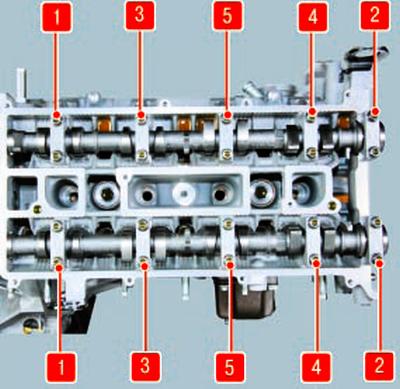
Pic. 5.37. The order of tightening the bolts of the camshaft bearing caps.
NOTE: Before removing the 2.3L Duratec-HE camshaft bearing caps, you must also remove the variable valve timing solenoid valve by disconnecting the harness connector and removing the intake camshaft bearing cap bolt.
4. Remove the camshaft bearing caps.
WARNING: Camshaft bearing caps are marked with serial numbers.
WARNING: Remember or write down the location of the covers in order to install them in their original places: the covers are processed together with the cylinder head and it is forbidden to depersonalize them.
WARNING: When installing, keep in mind that the marks are on the outside of the covers.
5. Remove camshafts.
6. Examine camshafts.
The surfaces of the bearing journals and cams must be well polished and without damage. On the working surfaces of the necks, scoring, nicks, scratches, aluminum enveloping from the bearing seats in the block head are not allowed. If there are signs of seizing, overheating, deep scratches or wear in the form of a cut on the working surfaces of the cams, replace the shafts.
WARNING: Grinding the camshaft cams to eliminate stepped wear is prohibited, since changing the size of the cam profile will disrupt the valve timing.
7. In workshops equipped with special tools and fixtures, you can check the radial runout of the camshaft journals. If the runout is greater than 0.02 mm or the journals are misaligned, replace the shaft as it cannot be straightened.
8. Lubricate the beds of the camshafts with clean engine oil and lay the camshafts in them in such a position that none of the cams rests with the highest part of its toe on the valve lifter adjusting washer.
9. Establish covers of bearings of camshafts.
10. Clean the grooves of the cover and the mating plane of the head of the block from the remnants of the old gasket.
11. Tighten bolts of fastening of covers of bearings of camshafts in the order shown on fig. 5.37, in three stages: 1st - evenly tighten the bolts for half a turn each until the bearing caps come into contact with the surfaces of the cylinder head; 2nd - tighten with a torque of 7 Nm (0.7 kgf·m); 3rd - tighten by 45°.
12. Press the camshaft oil seals into the sockets of the front camshaft bearing caps (see Replacing camshaft seals).
13. Install the rest of the removed parts in the reverse order of removal.
Visitor comments