– traces of oil on any surface of a belt;
- signs of wear of the toothed surface, cracks, undercuts, folds and delamination of the fabric from the rubber;
– cracks, folds, depressions or bulges on the outer surface of the belt;
- Loosening or delamination on the end surfaces of the belt.
WARNING: A belt with traces of engine oil on any surface must be changed without fail, as the oil quickly destroys the rubber. Cause of oil on the belt (usually this is a violation of the tightness of the seals of the crankshaft and camshaft) must be eliminated immediately.
NOTE: Work on a manhole, overpass or, if possible, on a lift.
You will need: special tools for locking the camshafts and crankshafts and the timing belt tensioner pulley, a socket wrench «on 10», box wrenches or sockets «for 8», «at 13», key «at 18».
1. Remove the A/C compressor drive belt (cm. «Replacing the A/C Compressor Drive Belt») and accessory drive belt (cm. «Accessory drive belt replacement»).
2. Remove generator (cm. «Removal and installation of the generator»).
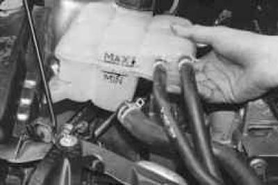
3. Remove the expansion tank from the brackets on the body and move it aside without disconnecting the hoses.
4. Securely support the engine.
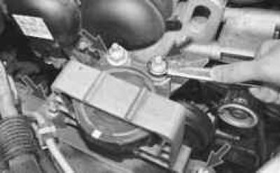
5. Remove the right front power unit suspension support by unscrewing the two nuts securing it to the bracket on the engine and unscrewing the two bolts securing it to the engine compartment mudguard.
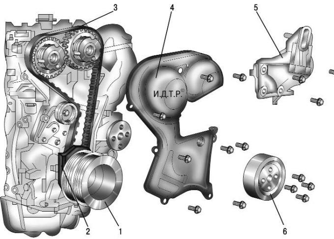
Pic. 4.13. Engine components removed when replacing the timing belt: 1 - crankshaft pulley; 2 - the lower cover of the timing belt drive; 3 - timing belt drive; 4 - front cover of the timing belt; 5 – arm of the right suspension support of the power unit; 6 - water pump pulley
6. Remove pulley 6 (pic. 4.13) water pump by unscrewing the four bolts of its fastening.
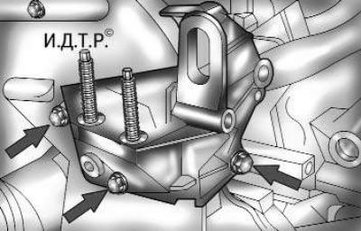
Pic. 4.14. Fastening of an arm of the right support of a suspension bracket of the power unit
7. Remove the bracket 5 of the right suspension support of the power unit by unscrewing the three bolts of its fastening (pic. 4.14).
8. Remove front cover 4 (see fig. 4.13) timing belt drive by unscrewing the eight bolts of its fastening.
9. Set the transmission lever to neutral position.
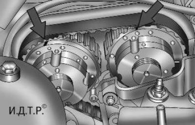
Pic. 4.15. Alignment marks on VCT mechanisms
10. Turn the engine crankshaft by the bolt of its pulley so that the marks on the VCT mechanisms (valve timing changes) camshafts were installed, as shown in fig. 4.15 (eleven o'clock on the clock face).
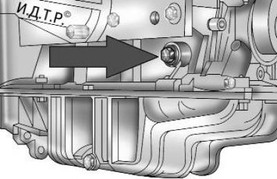
Pic. 4.16. Hole plug for installing the crankshaft fixing rod
11. Turn out the plug located in a forward part of the block of cylinders on the right (pic. 4.16), and install the fixing rod into the opened hole until it stops against the crankshaft. Carefully turn the crankshaft by the bolt securing its pulley until the shaft stops with the fixing rod.
NOTE: The fixing rod is a cylindrical piece about 65 mm long, stepped in diameter. Part of small diameter rod (4 mm), 10 mm long is a shank included in the groove of the crankshaft. The rest of the cylindrical part of a larger diameter (8 mm) serves as a guide in the bore of the cylinder block.
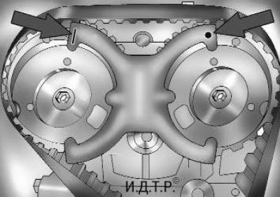
Pic. 4.17. Fixing the camshafts from turning with a special tool
12. Fix the camshafts from turning by installing a locking device in the special grooves in the housings of the VCT mechanisms (pic. 4.17). Set the fixture so that the marks on the branches of the fixture are at the top, and the mark in the form of a line should be on the side of the exhaust camshaft, and the mark in the form of a dot should be on the intake side.
13. Engage IV gear in a manual transmission (or set the automatic transmission selector to position «P» – parking) and brake the vehicle with the parking brake to prevent the engine crankshaft from turning.
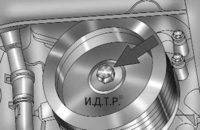
Pic. 4.18. Crankshaft pulley and its fastening
14. Turn out a bolt of fastening of a pulley (pic. 4.18) to the toe of the crankshaft and remove the pulley.
WARNING: The crankshaft pulley bolt must not be reused.
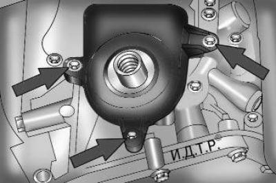
Pic. 4.19. The lower cover of the timing belt drive and its fastening
15. Turn out three bolts of fastening of the bottom cover of a belt of a drive of the gas-distributing mechanism (pic. 4.19) and remove the cover.
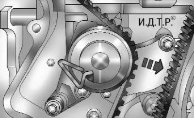
Pic. 4.20. Loose timing belt tension
16. Loosen the timing belt tension, for which move the leading branch of the belt as far as possible in the direction shown by the arrow in fig. 4.20. In this case, the tension roller will move to its original position. Fix the tension roller in this position by inserting a metal rod of suitable diameter into the holes of the roller and its bracket.
17. Remove the belt from the gear pulleys of the VCT mechanisms, the crankshaft and the tension roller.
WARNING: Do not rotate the crankshaft with the timing belt removed, as the pistons will damage the valves.
18. Put a new belt on the gear pulley of the exhaust camshaft VCT mechanism. Tension the drive belt and slide it over the intake camshaft VCT sprocket. Next, tighten the drive branch of the belt and put it on the crankshaft toothed pulley. Get the driven branch of the belt behind the tension roller.
19. Check the correct installation of the belt on the toothed pulleys and remove the fixing rod from the holes of the tension roller and its bracket. In this case, the tension roller spring will set the required belt tension.
20. Install the lower timing belt cover and crankshaft pulley. Tighten the crankshaft pulley bolt in two stages:
1st - tighten the bolt to 40 Nm (4.0 kgf·m);
2nd - tighten the bolt by 90°.
21. Remove the retainer from the VCT camshaft housings.
22. Remove the crankshaft fixing rod from the hole in the cylinder block (see point 11).
23. Engage the gearbox in neutral, turn the crankshaft two turns and stop it in a position where the marks on the VCT mechanism housings are in the position shown in fig. 4.15.
24. Install the fixing rod in the hole of the cylinder block (see point 11) and carefully tighten the crankshaft until it locks with the rod.
25. Install the locking tool on the VCT mechanism bodies (see fig. 4.17). If the tool can be installed without difficulty, the timing belt is installed correctly. If the device cannot be installed (shifted valve timing), remove the belt, install the retainer and repeat the installation of the belt as described above.
26. If the timing belt is installed correctly, remove the fixing device from the VCT mechanism housings, remove the fixing rod from the hole in the cylinder block, reinstall the plug of this hole, tightening it with a torque of 20 N·m (2.0 kgf·m), and install all removed parts in the reverse order of removal.
Visitor comments