ONS and V6 engines up to 8/94
Removal
Note: At the factory, during assembly, the ignition distributor is set with an accuracy of up to half a degree. To indicate the precise adjustment, after its completion, the distributor and mounting bolt are sealed with sealant. Therefore, the ignition distributor should be removed and the ignition timing adjusted only if necessary.
Disconnect the negative (-) battery cable.
Caution: When the battery is disconnected, the contents of electronic memory devices, such as engine fault codes or radio codes, are erased. Before disconnecting, also read the instructions in the chapter "Removal and installation the battery".
Engine OHC: follow the high-tension wire from cylinder 1 to the ignition distributor. Mark the place where the high-tension wire is inserted into the distributor with a felt-tip pen or marker.
Unscrew the fastening screws or, using a screwdriver, press the 2 spring clamps of the distributor cap to the sides. Remove the cap together with the high-voltage wires and put it aside so that it does not interfere with further disassembly.
If equipped, disconnect the vacuum hose from the distributor.
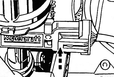
Disconnect the multi-pin plug connector at the distributor by pressing the "arrow" wire clamp.
Caution: When doing this, pull on the plug, not on the wire.
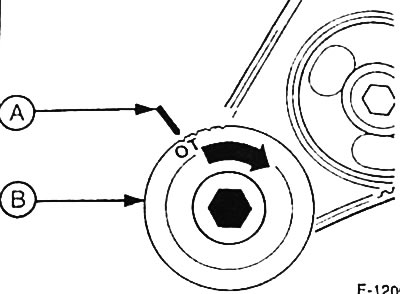
Turn the engine crankshaft to the position corresponding to the TDC of the combustion process for the piston of cylinder 1. To do this, shift the gearbox to neutral, tighten the handbrake and turn the crankshaft by the central bolt of the belt pulley "B" in the direction of its rotation "arrow" until the mark on the belt pulley coincides with the installation mark "A" on the crankcase.
ONS engine: at the same time, the center of the distributor rotor at the height of the housing edge must coincide with the mark applied at the location of the high-voltage wire for cylinder 1. If this is not the case, the crankshaft must be turned in the direction of its rotation by another full revolution (360°).
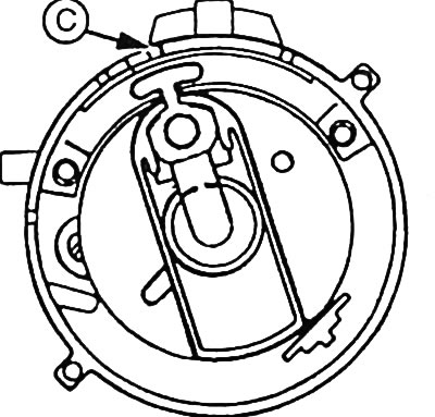
Engines with a displacement of 2.4 and 2.9 l: at the same time, the center of the distributor rotor must coincide with the "C" mark for cylinder 1. If this is not the case, the crankshaft must be turned in its direction of rotation by another full revolution (360°).
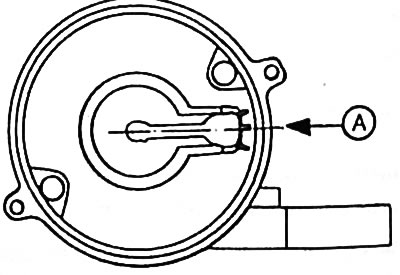
2.8L engine: At the same time, the center of the distributor rotor must coincide with the "A" mark for cylinder 1. If this is not the case, the crankshaft must be turned in its direction of rotation by another full revolution (360°).
Scrape off the sealing pack from the distributor mounting bolt.
Using a felt-tip pen or marker, draw a through mark along the base of the ignition distributor and the crankcase.
Remove the clamp bracket mounting bolt.
Remove the retaining clip and pull out the distributor.
Installation
Check whether the crankshaft is in the position corresponding to the TDC of the combustion process for the piston of cylinder 1.
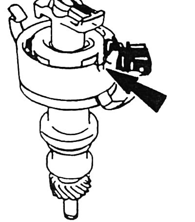
ONS engine: turn the distributor shaft so that the center of the distributor rotor is opposite the "arrow" recess closest to the plug connector.
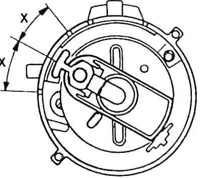
Engines with a displacement of 2.4 and 2.9 l: turn the distributor shaft so that the center of the distributor rotor is in the middle between the two marks.
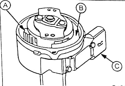
Engine with a working volume of 2.8 l: turn the distributor shaft so that the distributor rotor "B" is located, as shown in the figure, opposite the Hall sensor "A".
Place the distributor so that the marks made on the base of the distributor and the crankcase before removal match.
Insert the ignition distributor into the crankcase, slightly turning the rotor. After the distributor has fully entered the crankcase opening, check whether the marks on the base of the distributor and the crankcase still match. At the same time, the center of the distributor rotor must match the mark at the location where the high-voltage wire for cylinder 1 is installed.
If this is not the case, the ignition distributor can be turned a few degrees (approximately ±5°). If this is still not enough, the ignition distributor must be removed and reinserted again.
Apply the clamp and tighten the mounting bolt.
Connect the multi-pin plug connector of the ignition distributor.
Note: The wire clamp must secure the connector.
If the high-tension wires have been removed or a new distributor has been installed, insert the high-tension wires, starting with the marked wire for cylinder 1, in accordance with the firing order of the cylinders. The firing order of the cylinders for a 4-cylinder engine is: 1-3-4-2; for 6-cylinder engine: 1-4-2-5-3-6.
If available, connect a vacuum hose to the distributor.
Connect the ground (-) cable to the battery.
If available, set the clock and enter the anti-theft code for the radio.
Check and adjust the ignition timing angle, see p. 50.
DOHC engine up to 8/94
Removal
Disconnect the negative (-) battery cable.
Caution: When the battery is disconnected, the contents of electronic memory devices, such as engine fault codes or radio codes, are erased. Before disconnecting, also read the instructions in the chapter "Removal and installation the battery".
Disconnect the high-voltage wires from the distributor cap, having first marked them with adhesive tape so that they can be installed in their original places during assembly.
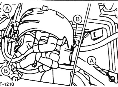
Unfasten the lower clamps "B" of the RFI shield and remove the upper screws "A".
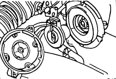
Loosen the slotted head screws securing the distributor cap and remove the cap.
Remove the ignition distributor rotor.
Installation
Insert the distributor rotor into the distributor shaft and turn it so that the rotor is fixed.
Place the distributor cap on and tighten it with slotted head screws.
Place the RFI shield over the cover and screw it in place or secure it with clamps.
Insert high-voltage wires in accordance with the existing marks. Engine cylinder firing order: 1-3-4-2.
Connect the ground (-) cable to the battery.
If available, set the clock and enter the radio theft protection code.
(The original article is posted at: FORDBOOK.RU)