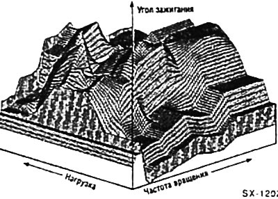
The optimum ignition advance angle depends primarily on the instantaneous values of the crankshaft speed and engine load. The instantaneous engine load is determined by the control unit based on the ratio of the crankshaft speed and the vacuum in the intake manifold or, respectively, the position of the throttle valve. Based on the ignition advance angle characteristics stored in the electronic memory, the control unit calculates the required ignition advance angle.
In a carburetor engine, additional adjustment of the ignition timing is carried out using a centrifugal adjustment mechanism and vacuum (a vacuum hose connects the ignition distributor to the intake manifold). In an engine with a Weber 2V-ISC carburetor, the ESC-H control unit additionally regulates the crankshaft speed at idle using a stepper motor at the carburetor.
The ignition distributor is equipped with a maintenance-free Hall sensor. The Hall sensor consists of a contactless permanent magnet and a screen fixed to the distributor shaft and rotating with it. Through the control unit, the Hall sensor determines the time for the ignition system to switch off and on the current through the ignition coil and thus sets the ignition advance angle.
Distributorless ignition system
DOHC engines with a working volume of 2.0-/2.3 l with 9/94 and V6 DOHC
The function of distributing high voltage to the spark plugs of individual cylinders is performed by stationary parts with electronic control, which have replaced the conventional mechanical distributor with a rotating rotor.
The ignition system has 2 or 3 ignition coils, respectively, which are attached in the spark plug area. The ignition system is synchronized using signals transmitted to the control unit by a pulse sensor. The pulse sensor is located on the side of the cylinder head and records the rotation frequency of the camshaft. The ignition system control unit is located at the end of the crankcase next to the expansion tank of the cooling system.
The injection and ignition systems have a common electronic control unit, which is equipped with a memory device for fault codes. It accumulates fault codes that occur in the engine electronics during trips. Before repairing the ignition system, it is necessary, first of all, to interrogate the memory device. The memory device is interrogated using a diagnostic device through the diagnostic connector located behind the cover on the left in the driver's footwell.
Since a car owner, as a rule, does not have a diagnostic device, it is recommended to print out the contents of the memory device of fault codes at the service station.