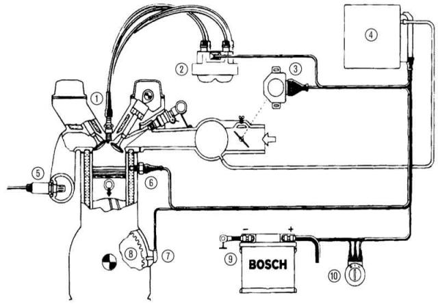
Basic design of a fully electronic ignition system
 |
|
1 - Spark plugs,
|
6 - Engine temperature sensor,
|
Early inductive energy storage ignition systems—consisting of an ignition coil, distributor, capacitor, distributor rotor, chopper contacts, and a high voltage ignition cable—helped, with their relatively limited flexibility, older carbureted engines sometimes hold up «on a leash»: ignition coil «produced» voltage capable of breakdown and a mechanical distributor once gave spark plugs a lot «fire». In the upper speed range, this happened with a modest pre-ignition, just before the top dead center of the piston, which was directly on the compression stroke. In other words: the periphery of the engine, all components for the preparation of a combustible mixture and valve actuators were more or less dependent on the static performance of the ignition system. Ignition systems with energy storage in inductance «distributed» sparkle with the flexibility of a matchbox.
This is not the case in the era of electronic engine control: behind the scenes and completely unnoticed by untrained eyes, electronic components are used «flammable» and flexible connections (see chapter Engines).
There is little chance without special equipment - for an amateur in a modern ignition system
For the amateur and ambitious «screwdriver» this can have consequences: Ignition systems firmly integrated into the engine management system, without special equipment, hardly offer starting points for proper homework. Also, under the hood of the Mondeo, sparks do not jump without «orders» transmission control devices (RSM) and different black boxes.
The inner life of these electronic components can, of course, be known with the necessary special knowledge and highly sensitive instruments. However, this will not give you the opportunity to take care of them and may even be disappointing: fully electronic ignition systems (VZ), have long had their childhood illnesses and meanwhile for a long time support the life of the car in full «juice». However, here it will still be useful to give a brief overview of the type «in a world of electronically controlled igniting sparks».
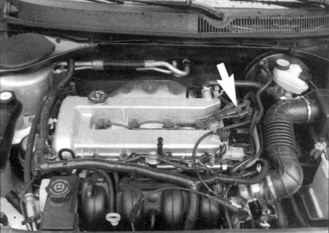 Touch control: Igniting sparks in the Mondeo. DuraTec-HE motors are equipped with a control unit (indicated by an arrow) directly on the cylinder head directly near the fourth cylinder. This module converts the onboard voltage of 12 volts to an ignition voltage of 30,000 volts. |
Constantly in «double packing» – igniting sparks in the Mondeo
By design, the twin spark ignition coils in the Mondeo deliver their high voltage to the spark plugs in «double packing»: the first spark ignites the fresh fuel mixture in the cylinder on the compression stroke, while the other «thrown in» on the ejection stroke in «opposite» cylinder. This is clearly seen in the example of the Duratec-HE engine: cylinders 1 and 4 as well as cylinders 3 and 2 always receive «their sparks» simultaneously.
PCM provides basic data - TFR sensor
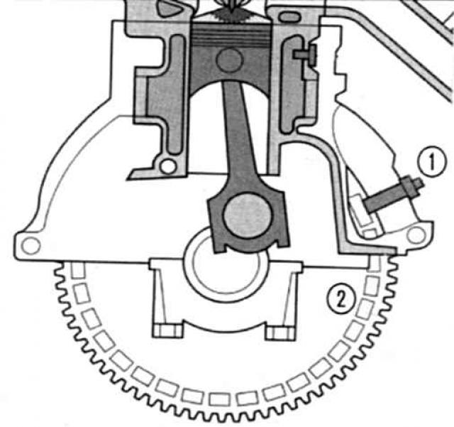
The signal from the crankshaft position sensor is primarily used as the basis for the calculation of each individual ignition spark (TFR). Its signal controls, after it has been digitized in PCM, the primary winding of the ignition coil. To do this, the PCM briefly interrupts the current supply to the PCM. This results in high voltage (ignition voltage), which is fed through the high voltage cable to the spark plugs and discharged there.
So that sparks appear in a timely manner - the engine control unit (RSM) with different spatial parametric characteristics
Behind «proper» ignition spark coordination in the Mondeo is the responsibility of PCM. Its memory stores, among other things, theoretical basic data on a wide variety of spatial characteristics of the ignition timing. In order to closely connect foggy theory with practice, the on-board computer processes the corresponding sensor signals from the engine periphery with a cycle of several milliseconds. For example, he completes his «information on the hard drive» current data from the crankshaft position sensor and knock sensor. In addition, prior to each gas exchange, the PCM communicates with the accelerator pedal, oxygen sensor, speed sensor, and various temperature and air flow sensors under the engine hood.
According to load condition (idle, part load, full load) and fresh air quality, the fuel mixture burns in the combustion chambers at different rates. In order to make the best possible use of the fuel energy, the black box changes the ignition timing parameter according to the load condition for each individual cylinder. The best moment accordingly occurs when the fresh fuel mixture ignites at the moment of maximum compression. In four-stroke engines, this is the point at which the piston moves from upstroke on the compression stroke to downstroke on the power stroke.
Execute in a timely manner – ignition and combustion
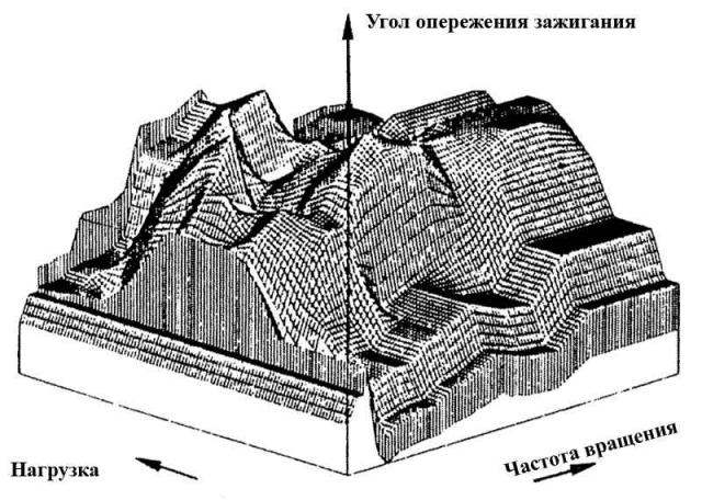 Three-dimensional characteristic: spatial parametric characteristic of the ignition timing. Each individual ignition spark in anticipation is prepared in terms of fuel consumption, torque, exhaust gas, distance from the engine knock limit, engine temperature, movement, and the like. Depending on the philosophy of the motor manufacturer, one or the other «point of view» receives a different priority. This procedure takes place on a spatial parametric characteristic of the ignition timing, three-dimensional «surfaces from mountains and valleys» with nearly 4,000 individually callable ignition timings. Supervision over it «landscape of craters» performed by the engine control unit (RSM). |
Naturally, the ignition timing does not exactly occur at top dead center (TDC). since it takes about a three-thousandth of a second before the mixture ignites. Therefore, igniting sparks, even during the upward movement of the piston, receive «green light».
The maximum combustion pressure, on the other hand, is set when the piston immediately passes TDC. Because the air-fuel mixture always takes the same amount of time to ignite, the ignition timing moves further away from TDC as the engine speed increases.
| TECHNICAL DICTIONARY | ||
|
Visitor comments