Distributor
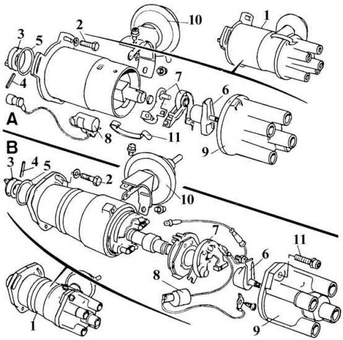
A – Bosch distributor; B – Lucas distributor; 1 – distributor assembly; 2 – mounting bolt; 3 – distributor drive; 4 – pin; 5 – sealing ring; 6 – distributor rotor; 7 – contact group; 8 – capacitor; 9 – distributor cap; 10 – vacuum ignition advance regulator; 11 – distributor cover mounting screw
Motorcraft Distributor
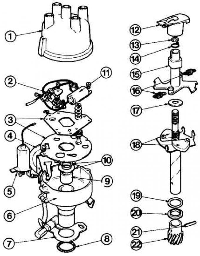
1–11 – fixed parts of the distributor; 12–22 – moving parts of the distributor; 1 – distributor cap (black); 2 – breaker; 3 – breaker plate; 4 – vacuum regulator; 5 and 11 – capacitor; 6 – body; 7 – fastening element; 8 – sealing ring; 9 – bearing; 10 – washer; 12 – distributor rotor; 13 – oil accumulator; 14 – retaining ring; 15 – cam; 16 – weight spring; 17 – washer; 18 – weights; 19 – distance ring; 20 – washer; 21 – pin; 22 – gear
Bosch distributor
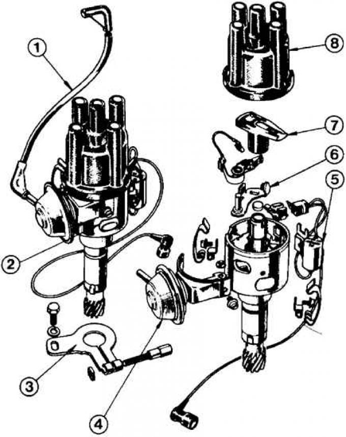
1 – vacuum tube from carburetor; 2 – distributor assembly; 3 – fastening element; 4 – vacuum regulator; 5 – capacitor; 6 – contacts; 7 – distributor rotor; 8 – distributor cap (brown)
Bosch OHV Engine Ignition Distributor
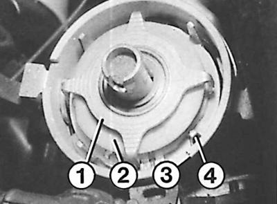
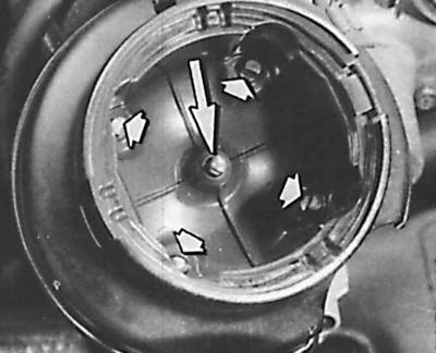
1 – control rotor; 2 – stator; 3 – first cylinder mark; 4 – stator pole
Electrode test locations on the distributor cap
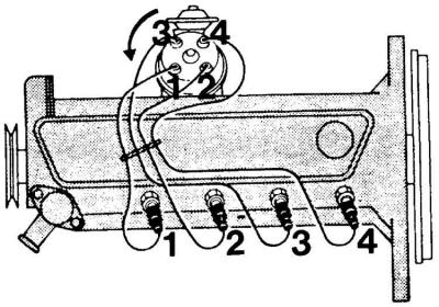
The order of connecting high-voltage wires
Removal and installation
1. Remove the high-voltage wires from the spark plugs and remove the distributor cap together with the wires.
2. Disconnect the wire from the negative terminal of the ignition coil and the vacuum tube of the ignition advance regulator from the distributor.
3. Turn the crankshaft to set the piston of the first cylinder to the TDC position and check that the distributor rotor is directed to the contact connected to the spark plug of the first cylinder.
Caution! Do not turn the crankshaft before installing the distributor.
4. Mark the position of the distributor rotor on the distributor cam and the distributor itself in relation to the cylinder block.
5. Unscrew the distributor mounting plate and, without turning the distributor, remove it, while making sure to mark the new second position of the distributor rotor on the cam.
6. When installing the distributor, the direction of the rotor must match the second mark on the distributor cam, since when the drive teeth are engaged, the rotor will turn counterclockwise.
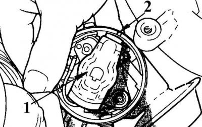
7. Install the distributor completely and check that the position of the distributor rotor (1) is aligned with the mark on the distributor cam (2) applied before removal. When the marks are aligned, tighten the distributor mounting bolt.
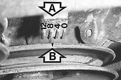
8. When installing a new distributor, turn the crankshaft to the TDC position of the first cylinder until the ignition timing marks align (A - marks on the cover, B - mark on the pulley).
9. Install the distributor above its seat so that the vacuum regulator of the ignition advance is opposite the guide tube of the oil level gauge, while it is necessary to take into account the rotation of the distributor rotor when the drive teeth are engaged.