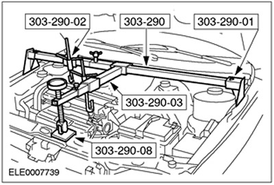
Special tool
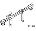 | Engine support beam 303-290A (21-140) |
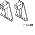 | Adapter for 303-290A (21-140) 303-290-01 (21-140-01) |
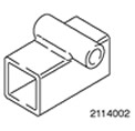 | Adapter for 303-290A (21-140) 303-290-02 (21-140-02) |
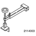 | Adapter for 303-290A (21-140) 303-290-03 (21-140-03) |
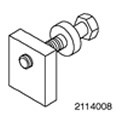 | Adapter for 303-290A (21-140) 303-290-08 (21-140-08) |
General equipment:
- Fixing clamps
- Gearbox jack
| Name | Specification |
| Automatic transmission fluid | WSS-M2C202-B |
Installation
1.
CAUTION: The torque converter must remain at the correct installation depth throughout the installation procedure.
NOTE: Before installing any transaxle bolts, the torque converter studs must be aligned with the flywheel bores.
NOTE: The torque converter hub must be fully engaged with the oil pump drive gear.
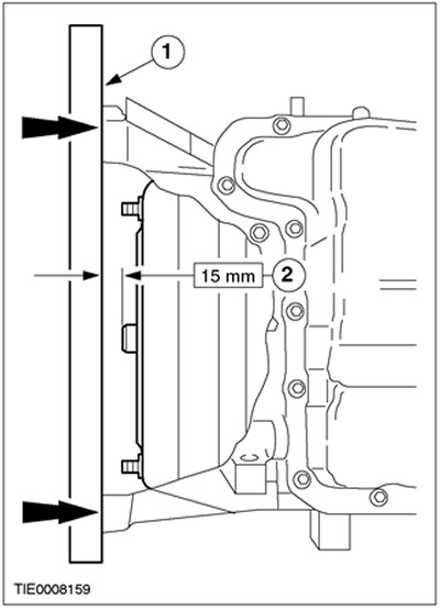
Check the installation depth of the torque converter.
1. Place a steel ruler against the automatic transmission flange in the transaxle.
2. Check the installation depth by measuring the distance between the transaxle flange and the torque converter centering lug. The correct size is 15 mm.
2.
NOTE: Make sure the pins are installed correctly.
Using a suitable transmission jack, install the transmission in the block with the drive axle. Remove the retaining clamps.
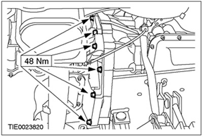
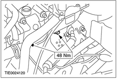
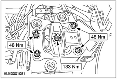
3. Install the right transmission mounting bolts in the block with the drive axle.
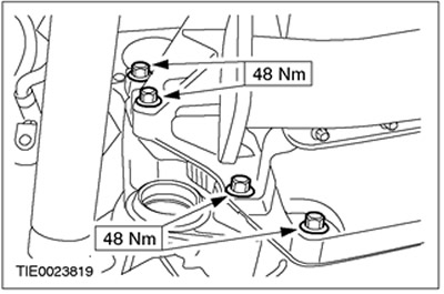
4. Install the left transmission mounting bolts in the block with the drive axle.
5.
NOTE: Make sure the starter ground cable is connected correctly.
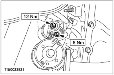
Install the starter.
6. Connect the starter electrical connections.
7.
NOTE: Install new torque converter mounting nuts.
Connect the torque converter to the flywheel. Install the cover (if equipped).
8. Lower the vehicle.
9. Install the oil filler line.
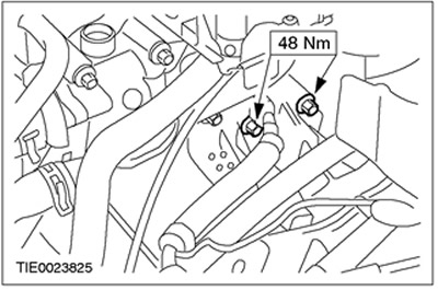
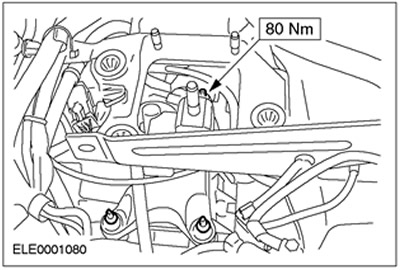
10. Install the upper transmission mounting bolts in the block with the drive axle.
11. Install the starter mounting bolts.
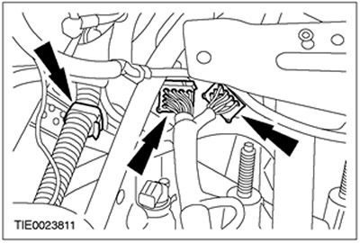
12. Connect the transmission wiring harness in the drive axle box to the transmission in the drive axle box.
- 1. Install the clamp.
- 2. Connect the plug connectors.
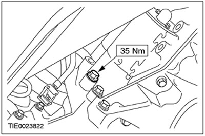
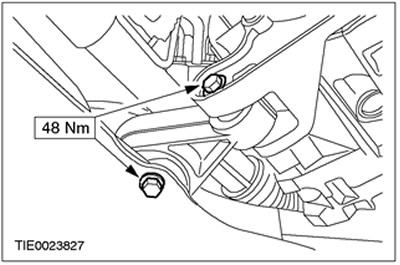
13. Install the rear engine and gearbox support bracket in the block with the drive axle.
14. Using special tools, lift the engine assembly with the gearbox in the block with the drive axle.
15. Install the rear engine mount assembly with the gearbox in the block with the drive axle.
16. Remove the special tools.

17. Raise and support the vehicle. Refer to Section 100-02 for additional information.
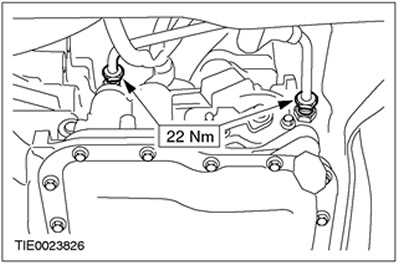
18. Connect the oil cooler lines to the transaxle.
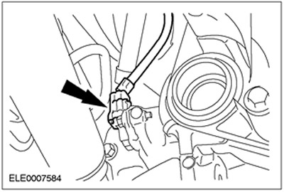
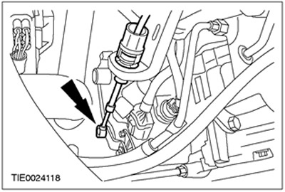
19. Connect the secondary shaft speed sensor (OSS) connector.
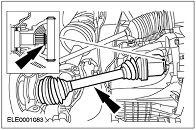
20.
CAUTION: Support the axle shaft. The inner joint should not be deflected at an angle exceeding 18 degrees. The outer joint should not be deflected at an angle exceeding 45 degrees.
CAUTION: Do not damage the axle shaft oil seal.
CAUTION: Make sure the snap ring is installed correctly.
NOTE: Install a new snap ring.
Connect the left axle shaft to the transaxle.
21.
CAUTION: Support the axle shaft. The inner joint should not be deflected at an angle exceeding 18 degrees. The outer joint should not be deflected at an angle exceeding 45 degrees.
CAUTION: Do not damage the axle shaft oil seal.
Connect the right axle shaft to the transaxle.
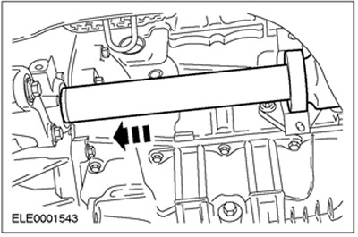
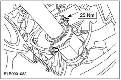
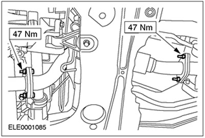
22.
NOTE: Install a new right axle shaft intermediate bearing cover and locknuts.
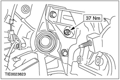
Install the right axle shaft intermediate bearing cover.
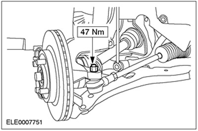
23.
WARNING: Install new lower control arm ball joint bolts and nuts. Failure to follow this instruction may result in personal injury.
Connect the lower control arms to the steering knuckles on both sides.
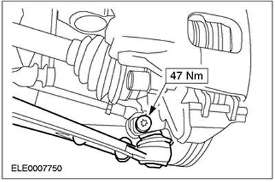
24.
WARNING: Install a new tie rod end nut. Failure to follow this instruction may result in personal injury.
Connect the left tie rod end to the steering knuckle.
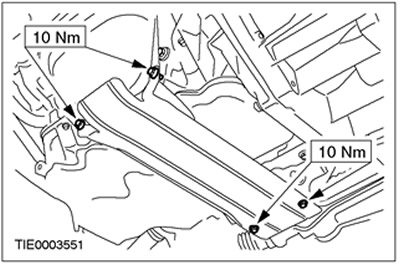
25. Install the flexible exhaust pipe.
26. Install the heat shield.
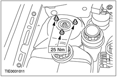
27. Install the right engine mount.
28. Install the left front wheel and tire assembly. Refer to Section 204-04 for additional information.
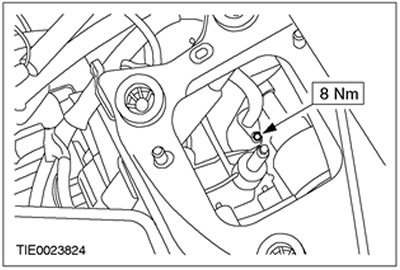
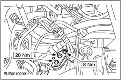
29. Connect the oil filler pipe and the gear selector lever cable mounting bracket to the transaxle.
30. Tighten the nuts of the upper suspension strut assembly with the spring (on both sides).
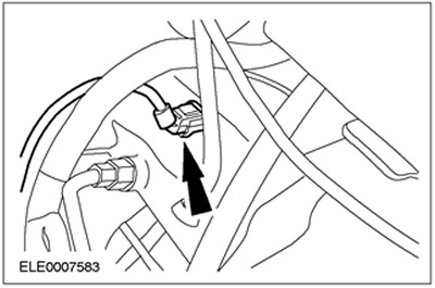
31. Connect the turbine shaft speed sensor (TSS) connector.
32. Connect the gear selector lever cable to the gear selector lever assembly.
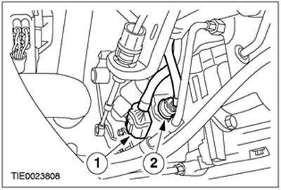
33. Connect the plug connectors to the gear selector lever assembly.
- 1. Connect the transmission range (TR) sensor connector.
- 2. Connect the automatic transmission plug connector to the drive axle block.
34. Adjust the shift cable. Refer to Section 307-05 for additional information.
35. Install the air cleaner inlet pipe.
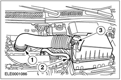
36. Install the air filter housing.
- 1. Connect the inlet hose to the throttle body.
- 2. Connect the engine crankcase ventilation hose to the air cleaner housing.
- 3. Connect the mass air flow (MAF) sensor connector.
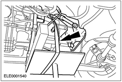
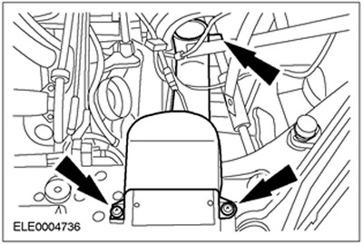
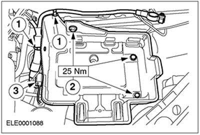
37. Install the battery tray.
- 1. Connect the wiring harness to the battery tray.
- 2. Install the bolts.
- 3. Connect the plug connector to the battery tray.
38. Install the battery. For additional information, refer to Section 414-01.
39. Fill the cooling system with coolant. Refer to Section 303-03 for additional information.
40. Fill the gearbox in the block with the drive axle with transmission fluid.
[For details, please visit the website: fordbook]