Special tool
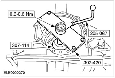
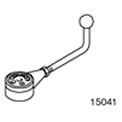 | Preload Measuring Device 205-067 (15-041) |
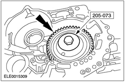
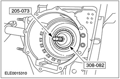
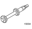 | Tool for installing the inner ring of the differential bearing 205-073 (15-034) |
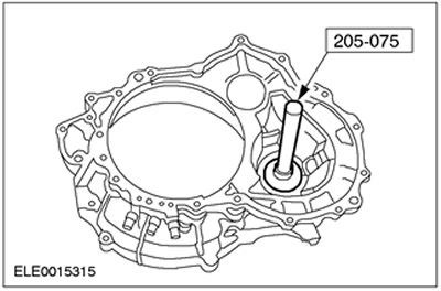
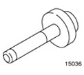 | Rear Wheel Hub Oil Seal Installer 205-075 (15-036) |
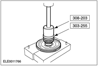
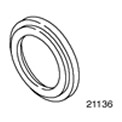 | Timing Gear Cover Oil Seal Installation Tool 303-255 (21-136) |
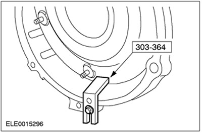
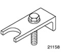 | Valve Spring Compressor 303-364 (21-158) |
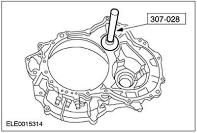
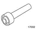 | Tool for installing oil seal of protruding section of crankcase 307-028 (17-002) |
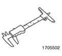 | Depth gauge for selecting adjusting shims 307-300-02 (17-055-02) |
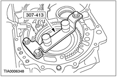
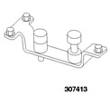 | Final Drive Locking Tool 307-413 (17-079) |
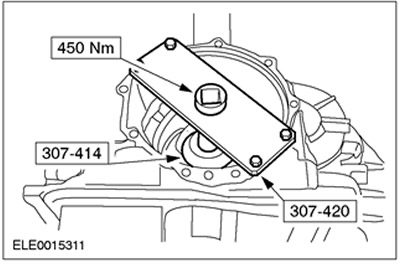
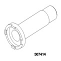 | Socket wrench for main gear nut 307-414 (17-080) |
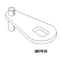 | TRS 307-415 (17-081) Sensor Alignment Tool |
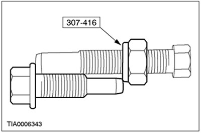
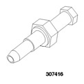 | Adjusting bolt for transmission band brake 307-416 (17-082) |
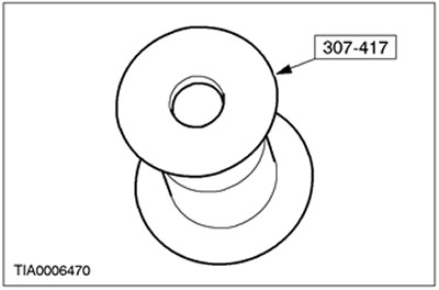
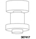 | Bearing Preload Measuring Device 307-417 (17-083) |
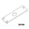 | Guide plate for 307-414 307-420 (17-085) |
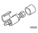 | 5th gear puller of primary shaft 308-082 (16-035) |
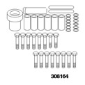 | Distance element for gearbox housing 308-164 (17-084) |
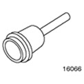 | Dual Differential Oil Seal Installer 308-203 (16-066) |
| Name | Specification |
| Sealant for threaded connections | TN-YS5J-M4G9107-AA |
| Loctite 5699 | WSS-M4G-320-A3 |
Assembly
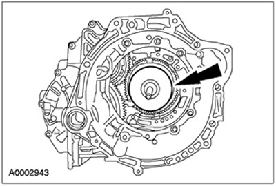
1. Using a press and special tool, install the main gear pinion bearing.
2. Install a new deformable washer.
3. Using the special tool, install the main gear pinion.
4.
WARNING: When installing the main gear drive bearing, hold the main gear drive pinion to prevent it from falling out of the gearbox housing in the drive axle box.
Rotate the gearbox in the block with the drive axle by 180 degrees.
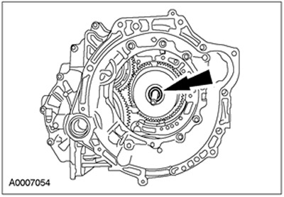
5. Using special tools, install the main gear pinion bearing.
6. Turn the gearbox in the block with the drive axle by 180 degrees.
7. Using the special tool, lock the main drive pinion.
8. Turn the gearbox in the block with the drive axle by 180 degrees.
9.
NOTE: A high tightening torque value (in the range of 400-450 Nm) is necessary to compress the deformation washer to ensure correct bearing preload.
NOTE: If the preload is too high, a new compression washer must be installed.
Using the special tools, tighten the nut to achieve the required preload.
10. Rotate the gearbox in the block with the drive axle by 180 degrees.
11.
NOTE: Make sure the final drive turns.
Release the special tool.
12. Rotate the gearbox in the block with the drive axle by 180 degrees.
13.
CAUTION: Make sure the bearing preload is within specification.
NOTE: Rotate the gear ten times to ensure the bearings are properly seated.
Using special tools, measure the turning torque.
14. Once the correct turning torque has been reached, score the nut to prevent it from loosening.
15. Rotate the gearbox in the block with the drive axle by 180 degrees.
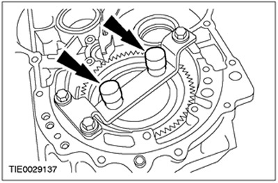
16. Install the pinion shaft gears into the gearbox housing in the block with the drive axle.
17. Install the parking latch return spring.
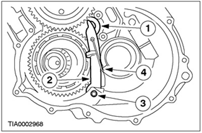
18. Connect the parking pawl return spring.
- 1. Install the parking pawl support.
- 2. Install the lever.
- 3. Install the cotter pin.
- 4. Connect the latch spring.
19. Install the parking latch cover.
20. Install the differential box assembly.
21. Install the outer bearing rings.
22. Install special tools.
23.
NOTE: The torque converter housing cover must be installed evenly; otherwise the result will be incorrect axial clearance.
Assemble the gearbox in block with the drive axle to measure the axial clearance.
- 1. Install the torque converter housing.
- 2. Install the long bolts and install the torque converter housing.
- 3. Install the short bolts.
24. Remove the torque converter housing.
- 1. Remove the bolts.
- 2. Remove the torque converter housing.
25.
NOTE: Do not move the plunger of the special tool; the setup is already done.
Remove special tools.
26.
NOTE: If the plunger is located above the contact surface, the reading will be incorrect.
To determine the correct shim thickness for the transmission shaft, measure the plunger depth with a special tool and select the correct shim. For more information, refer to the Specifications chapter in this section.

27.
NOTE: If the plunger is located above the contact surface, the reading will be incorrect.
To determine the correct differential shaft shim thickness, measure the plunger depth on a special tool and select the correct shim. For more information, refer to the Specifications chapter in this section.
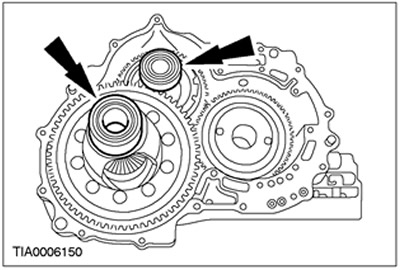
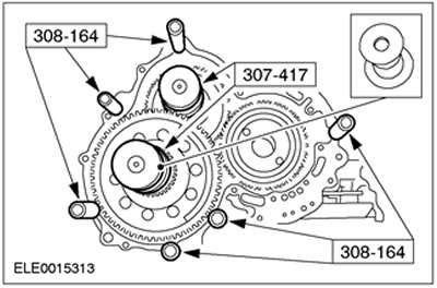
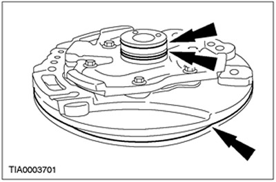
28. Using the special tool, install the correct transfer shaft gasket and differential case bearing outer race into the torque converter housing.
29. Using the special tool, install the correct differential shaft gasket and differential case bearing outer race into the torque converter housing.
30.
NOTE: Elements must be collected within 15 minutes.
Apply a 1mm bead of Loctite 5699 sealant.
31. Install the torque converter housing.
32. Install the servo piston return spring.
33. Install the servo block piston.
34. Install the O-ring.
35.
NOTE: The three bolts must be installed loosely and then tightened one at a time to evenly compress the servo piston return spring.
Install the servo piston cover.
36. Install the shift lever assembly and bolt.
37.
NOTE: Lubricate the O-ring before assembly.
Install new O-rings onto the hand lever shaft.
38. Install the hand lever shaft.
39.
NOTE: The roll pin should not be flush with the shift lever.
Install the hand lever shaft pin.
40. Loosely install the transmission range (TR) sensor.
41.
NOTE: The neutral/drive accumulator springs are thinner than the 1-2 accumulator springs.
Install the neutral/drive accumulator springs.
42. Install the neutral/shift accumulator piston.
43. Install accumulator springs 1-2.
44. Install the accumulator piston 1-2.
45.
NOTE: Inspect seals.
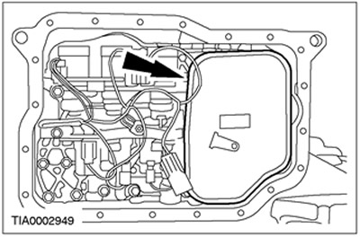
Lubricate and install the internal transmission wiring harness connector in the transaxle block.
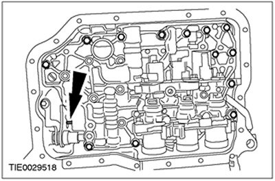
46.
NOTE: Make sure the manual valve is located on the manual control valve shift lever.
NOTE: Do not fully tighten the bolts at this stage.
Install the main control valve block.
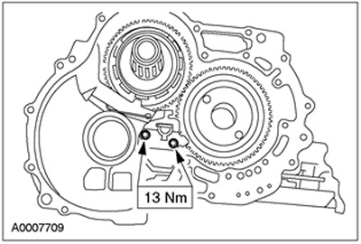
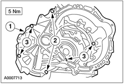
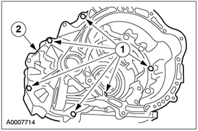
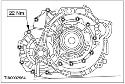
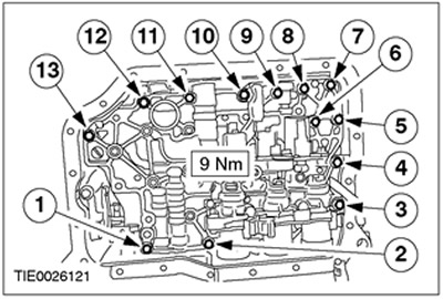
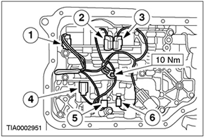
47. Tighten the main control valve block bolts. Tighten the bolts in the sequence shown.
48.
NOTE: It is necessary to mate the connectors in the same position as noted during disassembly. The color letters of the plug connectors are molded on the solenoid valve block.
Install the main control unit wiring, connect the plug connectors and install the ground wire bolt.
- 1. SSC solenoid valve; Color W (neutral white)
- 2. SSE Solenoid Valve: Color G (Green)
- 3. SSD Solenoid Valve: Color L (Blue)
- 4. EPC Solenoid Valve: Color B (Black)
- 5. SSA solenoid valve: Color N (neutral (grayish))
- 6. SSB Solenoid Valve: Color B (Black)
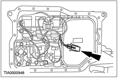
49. Install the transmission fluid filter.
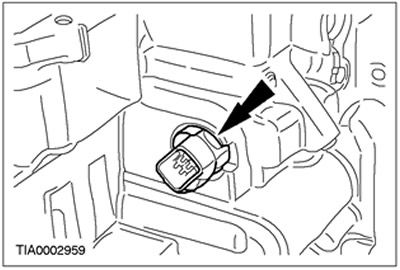
50. Connect the transmission fluid temperature (TFT) sensor.
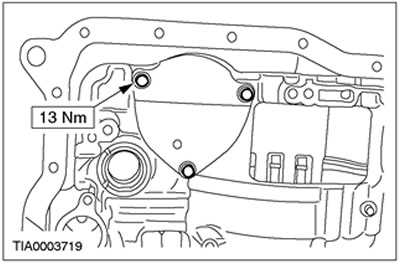
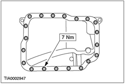
51. Apply a 1.5mm thick bead of Loctite 5699 sealant to the transmission fluid pan.
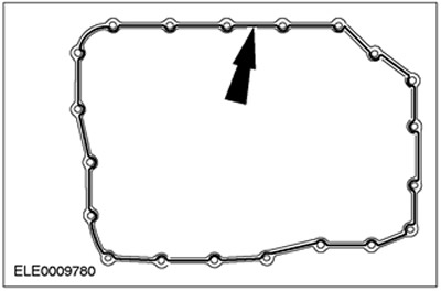
52. Install the transmission fluid pan and bolts.
53. Turn the gearbox in the block with the drive axle by 180 degrees.
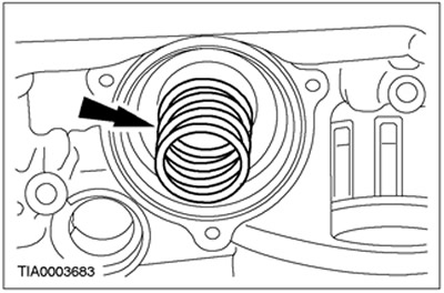
54. Install the piston of the low gear and reverse gear clutches.
55.
NOTE: Make sure the return spring is inserted with the tabs facing up
Install the return spring for the low and reverse clutches.
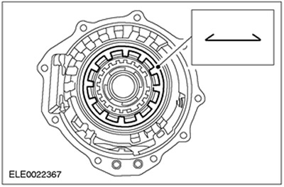
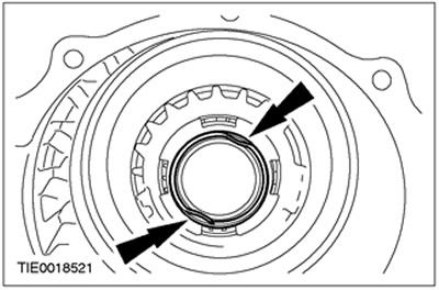
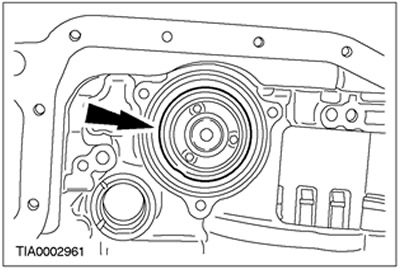
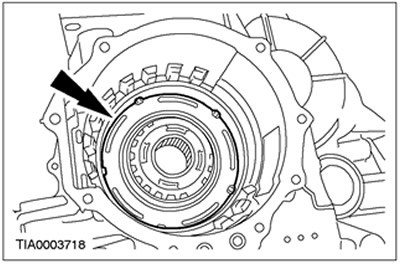
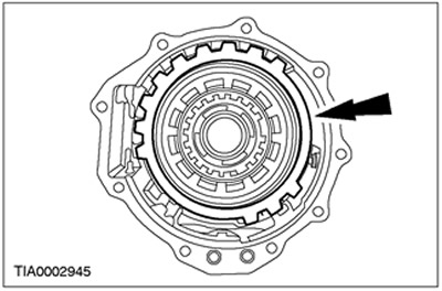
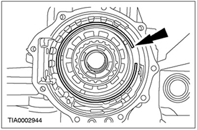
56. Install the beveled ring so that the outer surface faces upward.
57. Visually check the position of the beveled ring.
- 1. Make sure that the low and reverse clutch pistons are installed correctly.
- 2. Make sure the beveled ring is installed with the inner edge facing down.
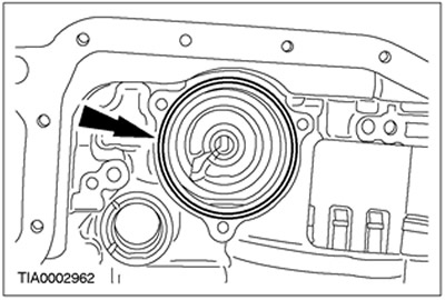
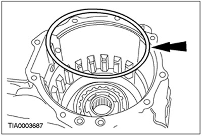
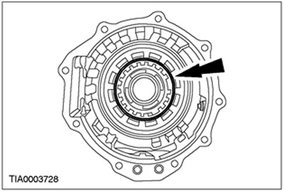
58. Install the inner race of the low gear single-acting clutch.
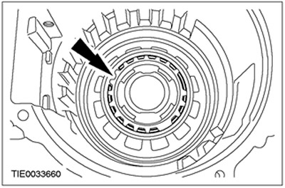
59.
NOTE: The snap ring joint must be at the 10 o'clock position.
Install the low gear one-way clutch retaining ring.
60. Install the low and reverse clutch disc and pressure plate.
61. Install the low and reverse clutch disc selective retaining ring.
- Check the coupling clearance. For more information, refer to the Specifications chapter in this section.
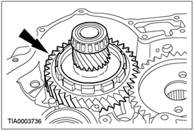
62.
NOTE: Before installing the planetary gear assembly, make sure the snap ring is installed.
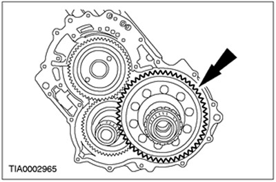
Install the planetary gear assembly.
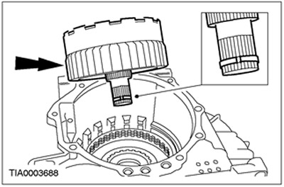
63.
CAUTION: The edge of the planetary gear assembly must be flush with the transaxle housing.
Inspect the planetary gear assembly.
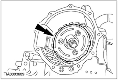
64.
CAUTION: The planetary gear must only rotate in a counterclockwise direction.
Check that the single-acting clutch is installed correctly.
- Rotate the planetary gear clockwise and counterclockwise.
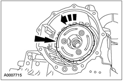
65. Install the intermediate and overdrive drum assembly.
66. Install the intermediate and overdrive band brake.
67. Install the direct clutch cylinder thrust bearing so that the rollers face up.
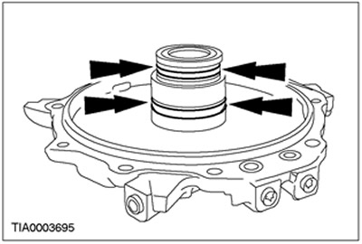
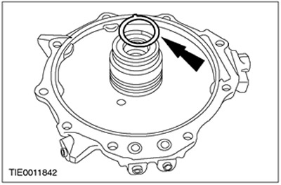
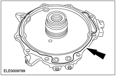
68. Install new seals between the end cover and the crankcase.
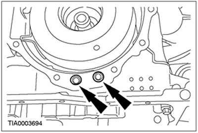
69. Install new end cover seals.
70. Install the direct drive clutch hub bearing adjusting shim and additional adjusting shim to increase the overall shim thickness to the specified value.
71.
NOTE: Make sure the cover is seated on both gaskets.
NOTE: Take measurements in several places and calculate the average gap.
Measure the gap between the transmission end cap in the drive axle unit and the transmission in the drive axle unit.
- 1. Install the transmission end cap in the drive axle box on the transmission in the drive axle box.
- 2. Measure the gap between the transaxle end cover and the transaxle.
72. Remove the end cover of the gearbox in the block with the drive axle.
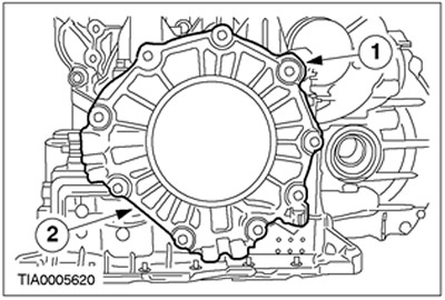
73. Select and install the correct direct drive clutch hub bearing gasket:
- Item 1 (Total combined thickness of the gasket used in modeling the transaxle end cover).
- Item 2 (measure the gap between the transaxle end cover and the transaxle housing).
- Item 3 (subtract the value in item 2 from the value in item 1 to get the correct total gasket thickness).
- Item 4 (subtract the total for item 3 from the minimum and maximum clearance values). For more information, refer to the Specifications chapter in this section.
- Measurement result: 0.25-0.50 mm
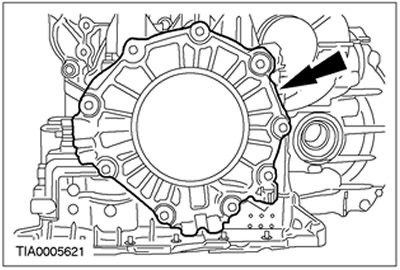
74. Apply a 1mm thick bead of Loctite 5699 to the transaxle end cover.
75. Install the gearbox end cover in the block with the drive axle.
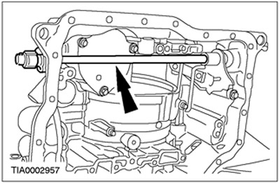
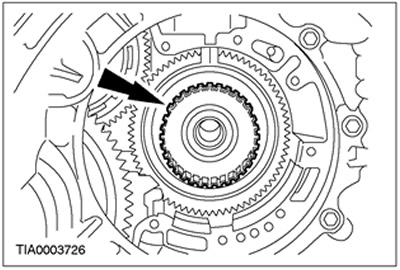
76. Using the special tool, compress the washer to specification, then release it three and a half turns.
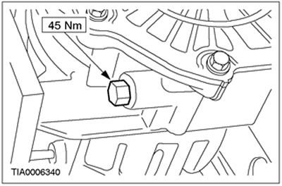
77. While holding the special tool, loosely install the nut into the transaxle housing, then remove the special tool without changing the position of the nut on the bolt.
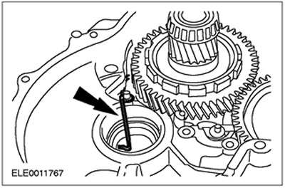
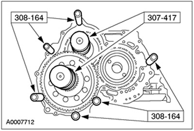
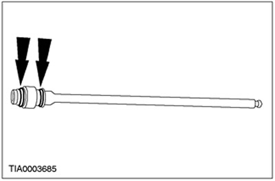
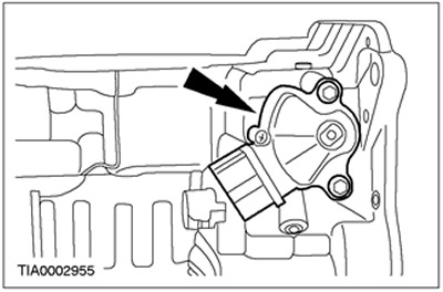
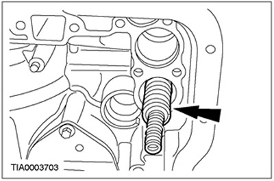
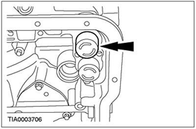
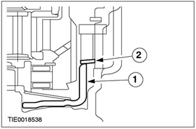
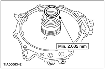
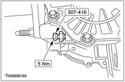
78. Using the special tool, select the band brake adjustment bolt, the length of which is measured from the end of the bolt to the surface of the nut, as shown.
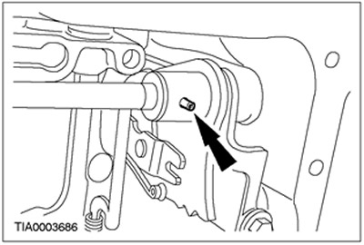
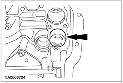
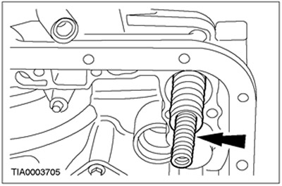
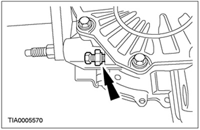
79.
NOTE: Apply thread sealant to the bolt.
Install the band brake anchor bolt.
80. Turn the gearbox in the block with the drive axle by 180 degrees.
81. Install the forward clutch hub.
82. Install the forward clutch assembly.
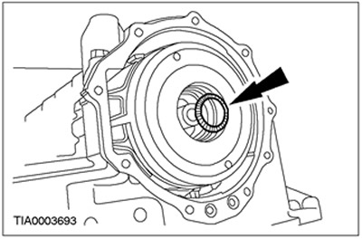
83. Install the forward clutch thrust washer.
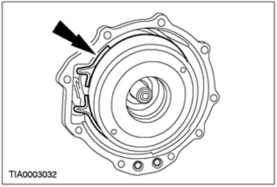
84. Lubricate and install new pump seals.
85.
NOTE: Do not lower the pump at this time.
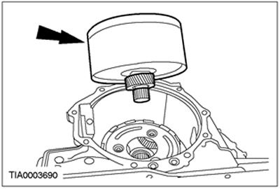
Install the pump.
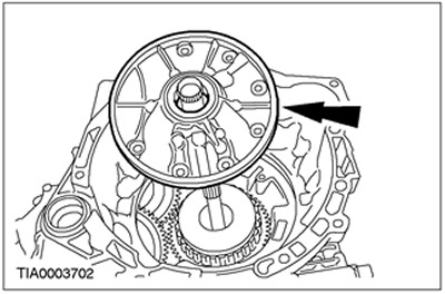
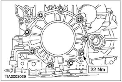
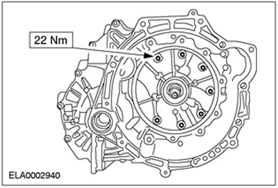
86. Install the pump.
- Use bolts to install the pump.
- Tighten the bolts using a crisscross pattern.
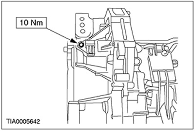
87. Install the secondary shaft speed sensor (OSS).
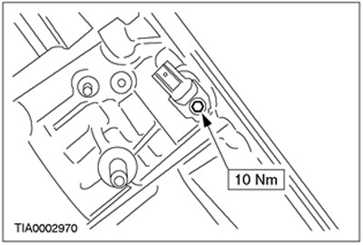
88.
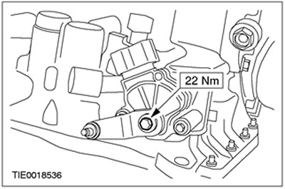
NOTE: Apply thread sealant to the bolt.
Install the turbine shaft speed sensor (TSS).
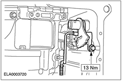
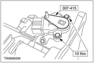
89. Using the special tool, align the TR sensor position and tighten the bolts.
90.
CAUTION: Do not use air tools when working on this bolt. Hold the hand control lever while tightening the hand control lever mounting bolt.
Install the manual control lever.
91. Install the torque converter.
92. Using the special tool, secure the torque converter.
(Content was created using data from this website: www.fordbook.ru)