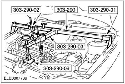
Special tool
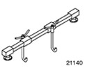 | Engine support beam 303-290A (21-140) |
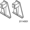 | Adapter for 303-290A (21-140) 303-290-01 (21-140-01) |
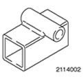 | Adapter for 303-290A (21-140) 303-290-02 (21-140-02) |
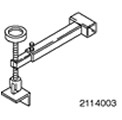 | Adapter for 303-290A (21-140) 303-290-03 (21-140-03) |
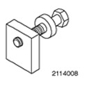 | Adapter for 303-290A (21-140) 303-290-08 (21-140-08) |
General equipment:
- Fixing clamps
- Gearbox jack
| Name | Specification |
| Automatic transmission fluid | WSS-M2C202-B |
Installation
NOTE: The location of the engine mounts and engine mounting pads as described is as viewed from the automatic transmission toward the engine.
1.
CAUTION: The torque converter must remain at the correct installation depth throughout the installation procedure.
NOTE: Before installing any transaxle-to-engine mounting bolts, align the torque converter studs with the engine drive plate holes.
NOTE: The torque converter hub must be fully engaged with the oil pump drive gear.
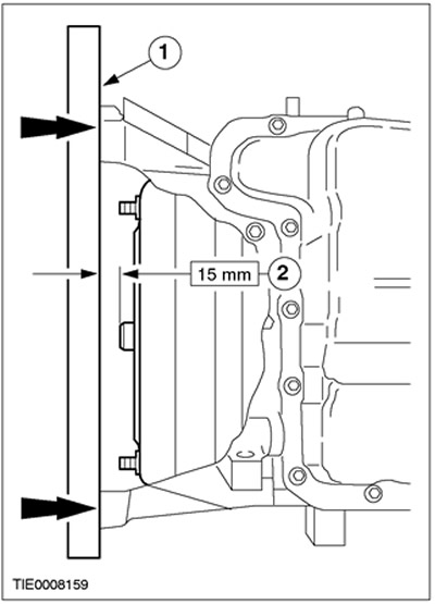
Check the installation depth of the torque converter.
1. Place a steel ruler against the automatic transmission flange in the transaxle.
2. Check the installation depth by measuring the distance between the transaxle flange and the torque converter centering lug. The correct size is 15 mm.
2. Raise and support the vehicle. Refer to Section 100-02 for additional information.
3.
NOTE: Make sure the pins are installed correctly.
Secure the transmission to the transaxle using suitable transmission clamps on a suitable transmission jack and install the transmission to the transaxle.
4.
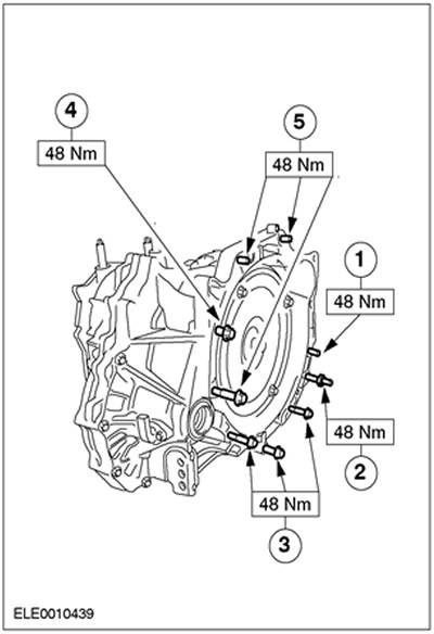
NOTE: Flange bolts come in different lengths.
Install the flange bolts.
- 1. M10 x 90.
- 2. M10 x 35 and M8 x 12.
- 3. M10 x 35.
- 4. M10 x 60.
- 5. M10 x 50.
5.
NOTE: Install new torque converter mounting nuts.
Connect the torque converter to the engine drive plate (four nuts).
6. Install the torque converter cover (if equipped).
7. Lower the vehicle.
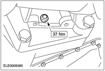
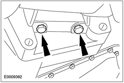
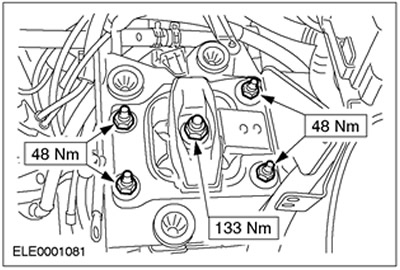
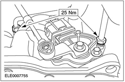
8. Install the rear engine mount bracket.
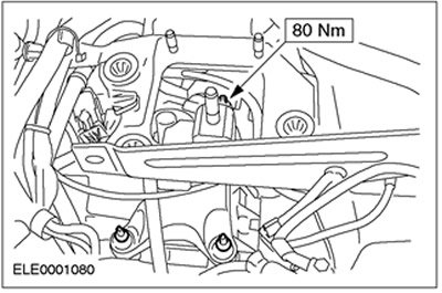
9. Install the rear engine mount.
10. Remove the special tools and remove the beam.
11. Raise and support the vehicle. Refer to Section 100-02 for additional information.
12.
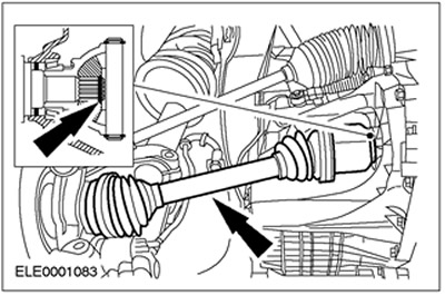
CAUTION: Support the axle shaft. The inner joint should not be deflected at an angle exceeding 18 degrees. The outer joint should not be deflected at an angle exceeding 45 degrees.
CAUTION: Do not damage the axle shaft oil seal.
CAUTION: Make sure the snap ring is installed correctly.
NOTE: Install a new snap ring.
Connect the left axle shaft to the transaxle.
13.
CAUTION: Support the axle shaft. The inner joint should not be deflected at an angle exceeding 18 degrees. The outer joint should not be deflected at an angle exceeding 45 degrees.
CAUTION: Do not damage the axle shaft oil seal.
Connect the right axle shaft to the transaxle.
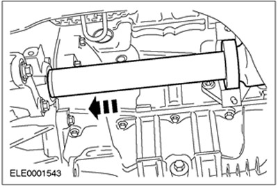
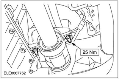
14.
NOTE: Install a new intermediate shaft bearing cap and locknuts.
Install the intermediate shaft intermediate bearing cover.
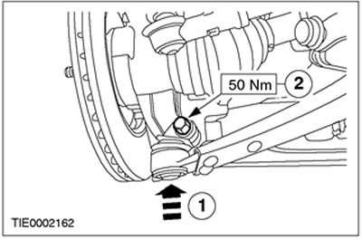
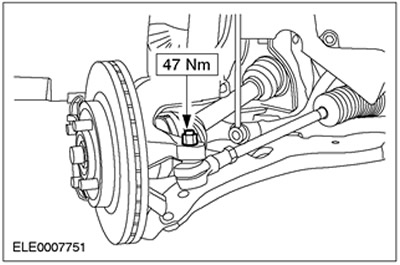
15. Connect the lower arms to the steering knuckles on both sides.
- 1. Connect the ball joint of the suspension arm.
- 2. Install the bolt.
16. Install the right engine roll limiter.
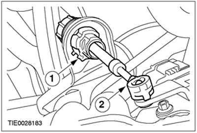
17. Connect the gear selector lever cable to the transaxle.
- 1. Connect the gear selector lever cable to the bracket.
- 2. Connect the gear selector lever cable.
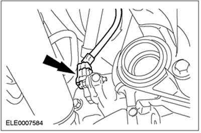
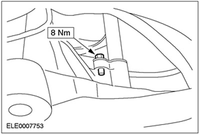
18. Connect the secondary shaft speed sensor (OSS) connector.
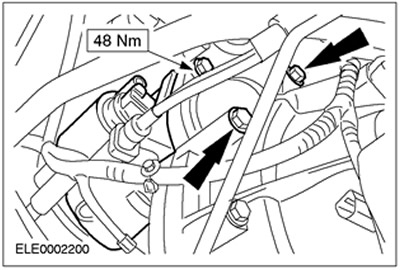
19.
CAUTION: Using an open-end wrench, hold the fluid line adapter to prevent it from turning.
Install the oil cooler lines.
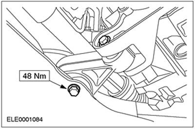
20. Install the left tie rod end.
21. Screw in the starter bolts.
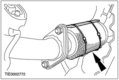
22. Connect the exhaust pipe and three-way catalytic converter (TWC).
23. Remove the retaining clamp.
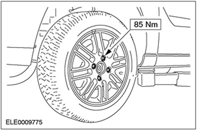
24. Install the left front wheel.
25. Lower the vehicle.
26. Install the transmission fluid level indicator dipstick tube.
27. Install the transmission fluid level indicator dipstick tube bracket.
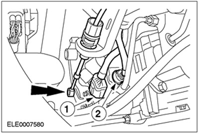
28. Connect the electrical connectors and connect the selector lever cable to the automatic transmission selector lever in the transaxle.
- 1. Transmission Range Sensor (TR) Plug Connector
- 2. Plug connector of the automatic transmission in the block with the drive axle.
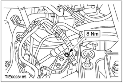
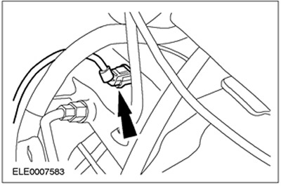
29. Connect the turbine shaft speed sensor (TSS) connector.
30. Install the air cleaner inlet pipe.
31. Adjust the transmission range selector cable. Refer to Section 307-05 for additional information.
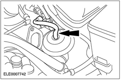
32. Connect the exhaust gas recirculation (EGR) vacuum line to the EGR valve.
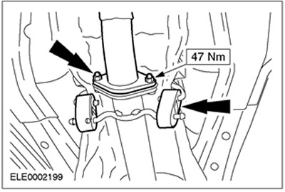
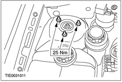
33. Tighten the nuts of the upper suspension strut assembly with the spring (on both sides).
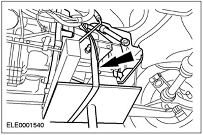
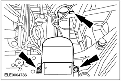
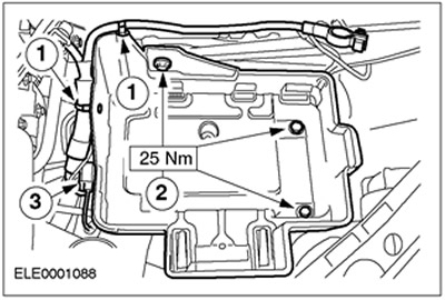
34. Install the battery tray.
- 1. Connect the wiring harness.
- 2. Screw in the bolts.
- 3. Connect the plug connector.
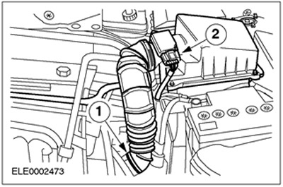
35. Install the air filter housing.
- Insert the air filter housing into the rubber grommets.
- 1. Connect the inlet hose.
- 2. Install the crankcase ventilation hose.
- 3. Connect the MAF sensor connector.
36. Install the battery. For additional information, refer to Section 414-01.
37. Enter the radio key code.
38. Reprogram preset radio stations.
39. Set the clock.
40. Fill the gearbox in the block with the drive axle with transmission fluid.
41.
NOTE: After disconnecting the battery cables and then reconnecting them, some abnormal vehicle handling may occur while the vehicle is learning its adaptive strategy. The vehicle must be driven for at least 16 km (10 miles) to learn its operating strategy.
Final operations:
- After the road test, check the fluid level and adjust it if necessary.
- Check the engine and cooling system for leaks (visual inspection).