|
STATES |
DETAILS/RESULTS/ACTIONS |
|
A1: CHECKING THE SWITCHING OF THE STOP LIGHTS. |
|
|
1Turn on the ignition. Press the brake pedal. |
|
|
• Are the brake lights on? |
|
|
→ Yes |
|
|
Go to A3 |
|
|
→ No |
|
|
Go to A2 |
|
|
A2: CHECKING THE CJB 54V FUSE. |
|
|
1Enter the OFF position. |
|
|
2CHECK F54 (15A). |
|
|
• Is the F54 fuse in order? |
|
|
→ Yes |
|
|
For additional information, see Section 417-01. |
|
|
→ No |
|
|
Install a new fuse. If the fuse blows again, recheck the system. Refer to Section 417-01 for additional information. |
|
|
A3: CHECKING THE IGNITION KEY REMOVAL INTERLOCK CIRCUIT. |
|
|
1Turn on the ignition, gearbox in position "P" ("Park"). |
|
|
• Can the ignition switch be turned to position "0" and can the key be removed from the ignition switch when the gear selector lever is in position "P"? |
|
|
→ Yes |
|
|
Go to A4 |
|
|
→ No |
|
|
Go to A8 |
|
|
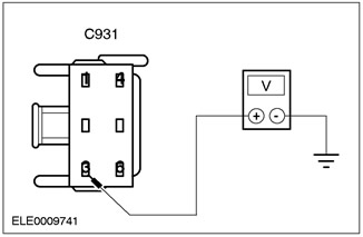
A4: CHECKING THE VOLTAGE SUPPLY TO THE PARKING LOCK SOLENOID. |
|
|
1Disconnect the Gear Shift Lever Assembly (C931). |
|
|
2Measure the voltage between pin 3 of C931 (green/white) and ground. |
|
• Is the voltage 0 V when the brake pedal is not pressed and is battery voltage registered when the brake pedal is pressed? |
|
|
→ Yes |
|
|
Go to A5 |
|
|
→ No |
|
|
Repair open in circuit 15S-TA33 between pin 1 and pin 3 of C444 (brake light switch). |
|
|
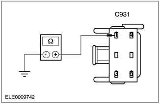
A5: CHECKING THE GROUNDING OF THE PARKING LOCK SOLENOID. |
|
|
1Measure the resistance between pin 1 of C931 (black) and ground. |
|
• Is the resistance less than 5 ohms? |
|
|
→ Yes |
|
|
Go to A6 |
|
|
→ No |
|
|
Repair open in circuit 31-TA34 between pin 1 C931 and ground. |
|
|
A6: CHECKING THE ELECTRICAL CIRCUIT OF THE GEAR SELECTOR LEVER. |
|
|
1Measure the resistance at the gearshift lever assembly connector (C931) between pins 3 and 1. The gearshift lever is in the "P" position. |
|
|
• Is the resistance between 20 ohms and 35 ohms? |
|
|
→ Yes |
|
|
Go to A7 |
|
|
→ No |
|
|
Replace the parking gear lock solenoid. |
|
|
A7: CHECKING THE FUNCTIONING OF THE PARKING LOCK SOLENOID. |
|
|
1Place the gear shift lever in positions "R", "N", "D", "1" and "2". - If necessary, unlock mechanically by following the description given in this section. |
|
|
• Does the resistance exceed 10 ohms in all of the above positions? |
|
|
→ Yes |
|
|
The parking position lock solenoid has no electrical faults. Check for mechanical faults. |
|
|
→ No |
|
|
Replace the parking position lock solenoid. |
|
|
A8: CHECKING FUSE F8 IN CJB. |
|
|
1CHECK F8 (30A). |
|
|
• Is the F8 fuse OK? |
|
|
→ Yes |
|
|
Go to A9 |
|
|
→ No |
|
|
Install a new fuse. Recheck the system. |
|
|
A9: CHECKING THE PARKING POSITION LOCK SWITCH. |
|
|
1Disconnect the Gear Selector Lever Lock (C931). |
|
|
2Connect the jumper wire between pin 2 of C931 (black/yellow) and ground. - Make sure that only pin 2 is grounded and no other. |
|
|
• Can the ignition key be removed with the jumper wire connected? |
|
|
→ Yes |
|
|
Go to A10 |
|
|
→ No |
|
|
Go to A11 |
|
|
A10: CHECKING THE SHIFT LOCK GROUND CIRCUIT. |
|

|
1Measure the resistance between pin 1 of C931 (black) and ground. |
|
• Is the resistance less than 5 ohms? |
|
|
→ Yes |
|
|
Replace the gear selector lever lock. |
|
|
→ No |
|
|
Repair the open in the electrical circuit 31-TA34 between pin 1 C931 and ground. |
|
|
A11: CHECKING THE VOLTAGE AT FUSE F8. |
|
|
1Measure the voltage at fuse F8 (30A). |
|
|
• Is battery voltage registered? |
|
|
→ Yes |
|
|
Go to A12 |
|
|
→ No |
|
|
Repair the open in the electrical circuit of fuse F8. |
|
|
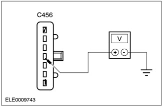
A12: CHECKING VOLTAGE AT THE IGNITION SWITCH. |
|
|
1Disconnect the Ignition Switch (C456). |
|
|
2Measure the voltage between pin 4 of C456 (red) and ground. |
|
• Is battery voltage registered? |
|
|
→ Yes |
|
|
Go to A13 |
|
|
→ No |
|
|
Repair the open circuit between fuse F8 (30A) and pin 4 of C456. |
|
|
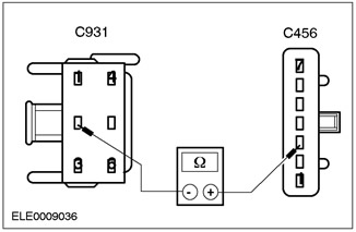
A13: CHECKING THE ELECTRICAL CIRCUIT 31S-TA34. |
|
|
1Measure the resistance between pin 3 of C456 (black/white) and pin 2 of C931 (black/yellow). |
|
• Is the resistance less than 1 Ohm? |
|
|
→ Yes |
|
|
The ignition key removal interlock solenoid located in the ignition switch is damaged. REPLACE the ignition switch. Refer to Section 211-05 for additional information. |
|
|
→ No |
|
|
Repair the open in the electrical circuit 31S-TA34 between pin 3 C456 and pin 2 C931. |
|
[The text was obtained in its entirety from the specified website www.FordBook.ru]