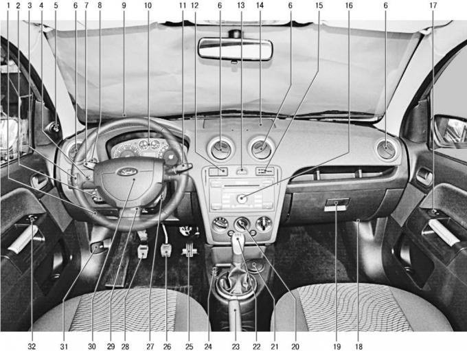
Fig. 1.6. Instrument panel and controls
The arrangement of the vehicle controls (Fig. 1.6) complies with the UNECE standards and regulations. For ease of use, the controls located on the instrument panel and other control panels are marked with the appropriate functional symbols.
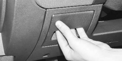
1 – drawer for small items. To use the drawer, open it by pulling the top edge of its front wall towards you.
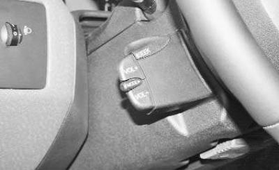
2 – audio system control joystick. The joystick can be used to adjust the volume and select other audio system modes without being distracted from driving while driving.
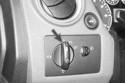
3 – External lighting switch. Turn the handle to select one of the following positions:
- 0 – external lighting off;
- side lights on;
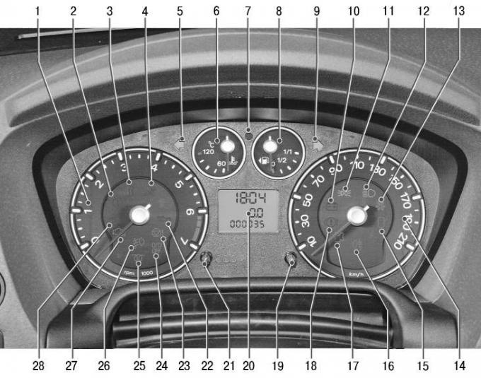
Fig. 1.7. Instrument cluster
Note: When the side lights are switched on, indicator lamp 11 lights up in the instrument cluster (see Fig. 1.7).
- low/high beam headlights on;
Note: When the high beam headlights are switched on, indicator lamp 12 lights up in the instrument cluster (see Fig. 1.7).
AUTO — automatic mode for switching on low beam headlights depending on the illumination (on vehicles equipped with an automatic low beam switching system);
Note: For the automatic low beam mode to work, the ignition must be on (the key in the ignition switch must be in position "II").
Note: In AUTO mode, the high beam headlights can only be turned on if the system has turned on the low beam headlights.
Note: In AUTO mode, the fog lights and tail lights are not turned on. To turn them on, turn the switch knob to the position.
- the parking lights are on. To turn on this mode, press the switch handle and turn it counterclockwise.
To turn on the fog lights, turn the switch handle to the position and pull it out one position.
Note: When the fog lights are switched on, indicator lamp 26 lights up in the instrument cluster (see Fig. 1.7).
To turn on the rear fog light, turn the switch handle to the position and pull it out two positions.
Note: When the rear fog light is switched on, indicator lamp 16 lights up in the instrument cluster (see Fig. 1.7).
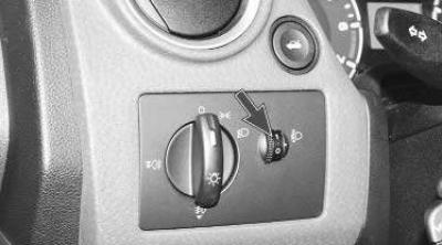
4 – headlight beam corrector regulator. By rotating the regulator wheel, depending on the vehicle load, the angle of the headlight beam is changed in such a way as to avoid blinding oncoming drivers. Combining the mark on the regulator handle and the number on the scale ensures the appropriate adjustment of the headlight position for the following vehicle load options:
- 0 – one driver or driver and front seat passenger;
- 1 - all seats are occupied;
- 2 – one driver and cargo in the trunk;
- 3 – all seats are occupied and cargo is in the trunk;
- 4 – all seats are occupied, cargo is in the trunk, the vehicle is used with a trailer.
Note: When operating the vehicle with a trailer, it may be necessary to move the electric corrector regulator to one position higher (for example, instead of position 2, set position 3).
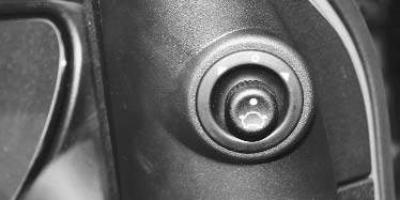
5 – block for adjusting the position of the outside rear-view mirrors (cm. "Rear view mirrors").
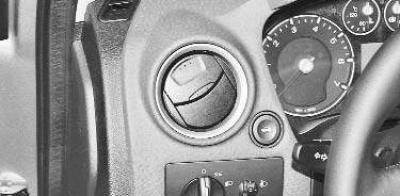
6 – nozzles of the ventilation and heating system of the passenger compartment. Designed to direct the air flow from a heater, air conditioner or ventilation system.
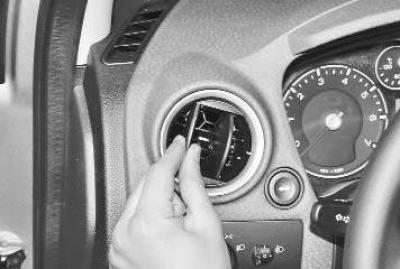
The direction of the air flow is changed by turning the flaps right-left or up-down.
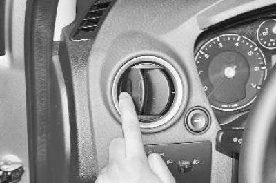
To fully open the air flow from the interior ventilation nozzle, press on the edge of the deflector or close it to stop the air flow.
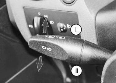
7 – lever for external lighting and direction indicators. The switch lever can occupy the following positions:
- I — right turn signals are on (fixed position);
- II — left turn signals are on (fixed position).
When the lever is moved to position "I" or "II", the control lamp 5 or 9 in the instrument cluster flashes (see Fig. 1.7). When the steering wheel is returned to the straight-ahead position, the lever is automatically reset to its original position. When changing lanes, to turn on the turn signal, simply press the lever in the direction of position "I" or "II" until you feel a noticeable resistance, without fixing the lever, and then release it. In this case, the turn signals will flash three times.
To switch between high and low beam headlights (the handle of the external lighting switch 3, shown in Fig. 1.6, must be in the position), move the switch lever towards you until it stops and release it.
Note: When the high beam is switched on, indicator lamp 12 lights up in the instrument cluster (see Fig. 1.7).
To signal with high beam headlights, pull the lever slightly towards you and release.
Note: If the ignition switch (lock) is in the "0" or "I" position, and the parking lights are on, a buzzer will sound when the driver's door is opened, reminding you to turn off the lights.
Depending on the configuration, there may also be an INFO button on the lever. By pressing the INFO switch, the necessary on-board computer menu windows are selected for setting up, resetting or selecting a submenu on the liquid crystal display.
8 – switch for remote drive for opening the tailgate.
9 – steering wheel.
10 – instrument cluster (cm. "Instrument cluster").
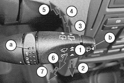
11 – Windscreen and tailgate wiper and washer switch lever turns on electrical circuits when the ignition is on.
The lever can be moved to the following positions:
- 1 – windshield wiper off;
- 2 – the wiper blades will complete one working cycle (non-fixed position);
- 3 – intermittent windshield wiper mode is on. The delay time between cycles is adjusted by rotary switch a: extreme lower position – minimum interval between cycles, extreme upper position – maximum;
- 4 – the first (low) windshield wiper speed is on;
- 5 – the second (high) speed of the windshield wiper is on;
Note: When you turn the windshield wiper cycle frequency control knob a from one extreme position to the other, the duration of the pause between windshield wiper cycles smoothly changes.
Note: When you press the washer switch b, the windshield wiper will automatically turn on along with the washer, and its blades will perform several working cycles after the button is released.
Note: If the vehicle is equipped with a headlight washer, pressing button b with the headlights on will also turn on the headlight washer.
- 6 – tailgate wiper is on;
Note: The rear window wiper is activated automatically (depending on the equipment) when reverse gear is engaged if the wiper lever is in position 2, 3, 4 or 5.
- 7 – tailgate wiper and washer are on.
12 – Rear window heating switch.
13 – hazard warning switch.
Note: The hazard warning lights operate in any position of the key in the ignition switch (lock).
14 – document box.
15 – coin holder. Depending on the configuration, an electronic stability program (ESP) switch or an airbag deactivation indicator lamp may be installed.
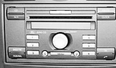
16 – audio system.
17 – Front passenger door window lift button.
18 – emergency fuel shut-off button (on cars with gasoline engines).
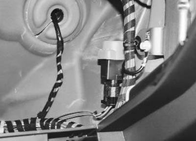
Note: This is what the emergency fuel shut-off button looks like (the glove compartment has been removed for clarity).
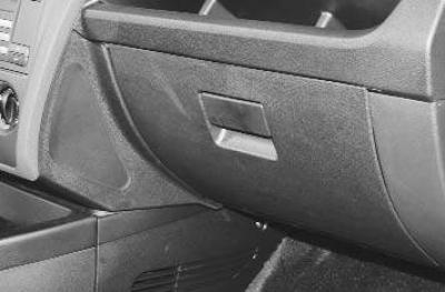
19 – storage box. It is used to store small items and opens when the lock handle is lifted up.
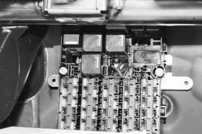
The fuse and relay box is located behind the drawer under the instrument panel. To access the box, open the drawer…
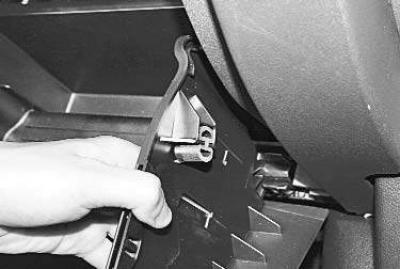
... bend the sides of the box, releasing their stops from engaging with the instrument panel, and remove the box.
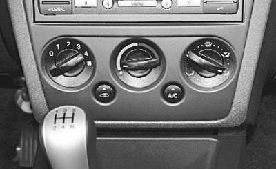
20 – Heating system control unit (air conditioning) and ventilation of the passenger compartment, see. "Heating (air conditioning) and ventilation of the passenger compartment".
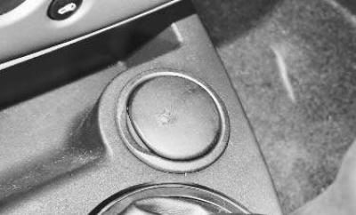
21 – ashtray.
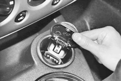
To use the ashtray, open its lid.
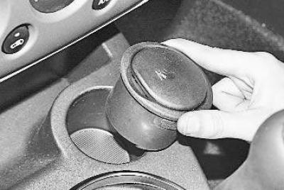
To clean, remove the ashtray from the floor tunnel lining.
22 – gearbox control lever (cm. "Gearbox control").
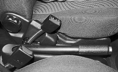
23 – Parking brake lever.
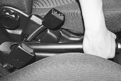
To apply the parking brake, lift the lever all the way up - the indicator light in the instrument cluster will light up red.
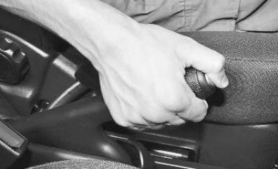
To release the brakes, pull the lever up slightly, press the button at the end of the lever handle and lower the lever all the way down - the indicator light should go out.
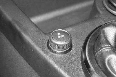
24 – cigarette lighter.
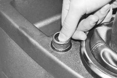
To use the cigarette lighter, press the button on its moving part (the key in the ignition switch is in position "I" or "II"). After the coil has heated for 10-20 seconds, the moving part will automatically return to its original position with a click.
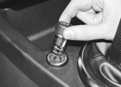
After this, remove the cigarette lighter for use.
Warnings!
- The cigarette lighter can be turned on again no earlier than after 20 seconds.
- Do not forcefully hold the cigarette lighter in the pressed position.
- Do not use the cigarette lighter socket to connect powerful electrical appliances (electric coffee maker, etc.) - this may damage the vehicle's electrical equipment.
- If the cigarette lighter button does not return to its original position within 30 seconds after switching on, remove the cigarette lighter from the socket to prevent the coil from burning out.
25 – accelerator pedal.
26 – brake pedal.
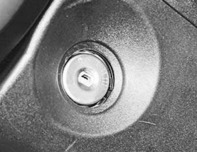
27 – ignition switch (lock), combined with an anti-theft device, is located on the right side of the steering column. The key in the lock can occupy one of four positions:
- 0 (lock) – ignition is off, anti-theft device is on when key is removed.
To ensure that the steering shaft is locked, turn the steering wheel to the right or left until it clicks.
To turn off the anti-theft device, insert the key into the ignition switch and, turning the steering wheel slightly to the right and left, turn the key to position "I";
Warning! Do not switch off the ignition or remove the key while driving: the steering will be locked and the vehicle will become uncontrollable.
- I (additional equipment) – ignition off, key cannot be removed, steering is unlocked. Power circuits for horn, exterior lighting, high beam headlights, radio equipment, cigarette lighter, etc. are on.;
- II (on) – ignition on, key cannot be removed, steering is unlocked. Ignition, instruments and all electrical circuits are on;
- III (starter) – ignition and starter are on, the key cannot be removed, the steering is unlocked. This position of the key is not fixed, when released, the key returns to position "II" under the force of the spring.
28 – clutch pedal.
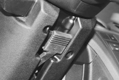
29 – steering column position lock lever (cm. "Adjusting the position of the steering wheel").
30 – sound signal on/off key. To sound the signal, press the power button.
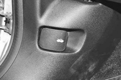
31 – hood lock drive handle (cm. "Hood").
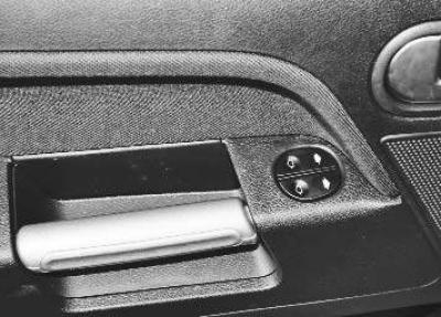
32 – window lift control unit.
(The material was copied from an information website: «www.fordbook.ru»)