Fuel pump adjustment
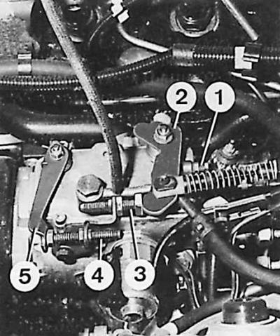
1 - adjusting bolt, 2 - fuel metering lever, 3 - residual flow adjustment bolt, 4 - idle speed adjustment bolt, 5 - idle speed lever
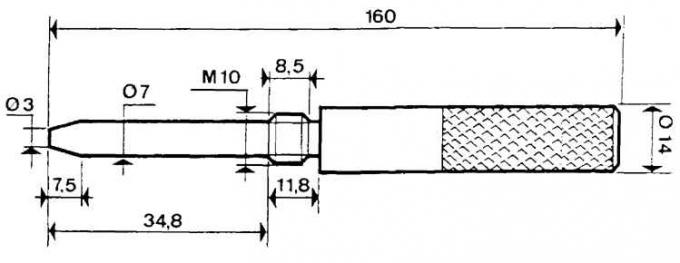
Dimensions of the mandrel for installing the crankshaft in the TDC position
Adjustment
Adjustment of the maximum speed
1. Check whether the accelerator pedal and the elements that transmit its movement move freely.
2. Start the engine and warm it up to normal operating temperature.
3. Bring the engine up to maximum speed.
Attention! The maximum permissible engine speed must not be exceeded; the engine should be at maximum speed for no more than 5 seconds.
4. If the maximum RPM is different from the recommended (see subsection 3.2.1.2.1), it is necessary to adjust using the adjusting bolt 1 (see fig. Fuel pump adjustment).
5. Check the time to reduce the speed from maximum to idle (no more than 5 seconds). If this time is longer, then it is necessary to adjust the idle speed and the residual flow, which prevents the engine from turning off.
Idling and residual flow adjustment
6. Install a 4mm thick plate between the bolt (3) residual flow adjustment (preventing engine shutdown) and lever (2) accelerator (fuel dosage) (see fig. Fuel pump adjustment).
7. Install a 20 mm thick plate between the lever (5) (see fig. Fuel pump adjustment) idle and restrictive bolt.
8. Set the position of the residual flow adjustment limit bolt so that the engine speed is 900±100 rpm.
9. Remove the 20 mm thick plate. The idle lever should return to contact with the adjustment bolt.
10. Remove the 4 mm thick plate.
Set the position of the idle speed adjustment bolt so that the engine speed is 870±20 rpm.
Check the behavior of the engine when the accelerator pedal is suddenly released. If the downtime is too long or too short and the engine stops, the adjustment must be repeated.
If the engine still stops, then tighten the residual flow adjustment bolt 1/4 turn if the engine speed is reduced too slowly, or unscrew 1/4 turn if the engine speed is reduced too quickly.
Attention! Do not tighten or loosen this bolt more than 1/4 turn.
Withdrawal
1. Disconnect ground wire from battery.
2. Unhook the spring hooks securing the upper casing of the timing system drive.
3. Place the vehicle on a stationary lift.
4. Unscrew the bolt securing the lower toothed belt casing, then loosen the second bolt and turn the casing down around the loosened bolt.
5. Lower the vehicle and remove the upper timing cover.
6. Mark the position of the accelerator pedal cable on the fuel pump lever and unhook the cable from it. Unscrew the bolt securing the lever and remove the cable.
7. Disconnect the electrical wire connector from the cold engine injection advance corrector.
8. Disconnect from the pump the connectors of the injection pipelines and the connectors of the return pipelines and the fuel dose corrector (close the openings with appropriate plugs or caps).
9. Remove the fuel pump bottom bracket bracket bolts. Unscrew the bolts securing the bracket to the engine block.
10. Disconnect the electrical connector of the engine shutdown solenoid valve (STOP valve).
11. Carefully disconnect vacuum line between turbocharger pressure correction valve and intake manifold.
12. Remove the alternator drive belt.
13. Remove the control hole plug from the engine block to set the piston of cylinder 1 to TDC.
14. Disconnect the pipes: fuel, return and turbocharger pressure correction.

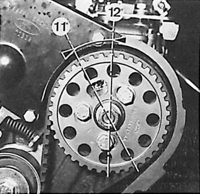
15. Using the appropriate wrench, turn the crankshaft pulley clockwise so that the fuel pump is in position "12 hours", and the camshaft cutout is in position "8 ocloc'k".
16. Rotate the engine crankshaft counterclockwise until the fuel pump is in position "11 o'clock".
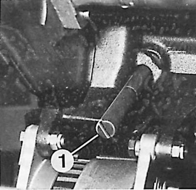
17. Screw the mandrel up to the stop (1) for setting the piston of 1 cylinder to TDC (see fig. Dimensions of the mandrel for installing the crankshaft in the TDC position).
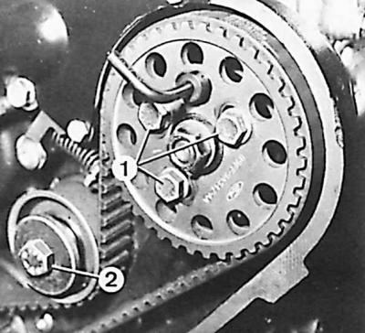
18. Loosen the bolt (2) fastening the tensioner roller of the timing belt of the fuel pump drive, loosen the toothed belt and tighten the bolt of the tensioner roller. Unscrew three screws (1) fastening the fuel pump pulley.
19. Remove toothed belt and fuel pump pulley.
20. Remove the fuel pump from the engine block.
Installation
Attention! When installing a new fuel pump, the plugs must be removed (plugs), blocking the openings of the fuel pipes and pour diesel fuel into the pump to facilitate the removal of air from it.
1. Check whether there is a mandrel for setting the piston of the 1st cylinder to TDC in the inspection hole on the side of the engine block.
2. Using the appropriate tool, install the hole in the fuel pump drive pulley against the hole in its housing.
3. Using Torx bolts, attach the front of the fuel pump housing to the engine block.
4. After removing the setting tool, install the pulley on the fuel pump drive flange and lightly tighten the pulley mounting bolts.
5. Position the fuel pump installer in the pulley and make sure it fits into the hole in the fuel pump drive flange.
6. Install the pulley mounting bolts in the middle position of the holes in the pump drive pulley.
7. Slide the toothed belt onto the fuel pump pulley.
8. Loosen the tensioner pulley bolt.
9. After the automatic movement of the tensioner (under the influence of a spring) tighten the tensioner pulley bolt.
10. Tighten the fuel pump pulley bolts to the correct torque.
11. Remove the setting mandrel and tool from the pump pulley and engine block.
12. Turn the engine crankshaft two full revolutions and set the hole in the fuel pump adjuster to position "12 hours", and the camshaft is in position "8 ocloc'k".
13. Rotate the engine crankshaft counterclockwise and set the fuel pump adjusting tool hole to position "11 o'clock".
14. Install a mandrel in the control hole of the engine block for setting the piston of the cylinder 1. to TDC and screw it up to the stop.
15. Carefully rotate the engine crankshaft until it rests against the locating mandrel screwed into the bore of the cylinder block.
16. Insert the fuel pump installation tools.
17. If it is not possible to insert the fuel pump installer into the fuel pump drive flange, loosen the drive pulley bolts and turn the pulley relative to the flange so that the installer can be screwed in until it stops.
18. Tighten the fuel pump drive pulley bolts and recheck the installation of the pump shaft.
19. Remove all setting tools and mandrel, and insert a plug into the inspection hole of the engine block.
20. Install the rear bracket bracket to the fuel pump and tighten the pump mounting bolts to the correct torque. Check that the fuel pump is properly attached.
21. Screw the fuel line connectors to the pump (injection, return, fuel supply and fuel dose regulator).
22. Connect the accelerator pedal cable according to the marking made when disconnecting it.
23. Connect the electrical wire connectors of the engine shutdown solenoid valve (STOP valve) and a cold engine injection advance corrector.
24. Install the timing belt upper cover.
25. Raise the car, turn the lower casing of the toothed belt of the timing belt up, insert the mounting bolt and tighten it and the bolt that serves as the axis of rotation of the casing.
26. Put on the alternator drive belt and tighten it.
27. Lower the vehicle and tighten the upper timing cover bolt.
28. Remove air from the fuel system.
Visitor comments