Gas distribution system
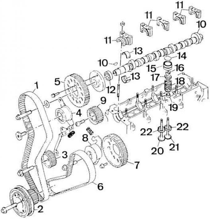
1 - Timing belt, 2 - Crankshaft pulley, 3 - Intermediate shaft pulley, 4 - Timing belt tensioner, 5 - Camshaft pulley, 6 - Fuel pump timing belt, 7 - Fuel pump pulley, 8 - Fuel pump timing belt tensioner, 9 - Middle pulley, 10 - Camshaft, 11 - Camshaft bearing caps, 12 - O-ring, 13 - Camshaft bearing shells, 14 - Valve clearance adjustment plate, 15 - Tappet, 16 - Crackers, 17 - Valve spring support cup, 18 - Valve spring, 19 - Oil deflector cap, 20 - Inlet valve, 21 - Exhaust valve, 22 - Valve seats
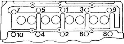
Cylinder Head Bolt Tightening Sequence
Installation of the gas distribution system
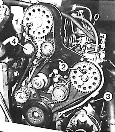
1 – device for installing the camshaft, 2 – device for installing the fuel pump, 3 – mandrel for installing the crankshaft in the TDC position, 4 – tensioner roller of the toothed belt drive of the gas distribution system
Location of the camshaft groove when installing the cylinder head
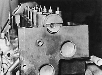
Before installing the head, make sure that the groove on the end of the camshaft eccentric is installed horizontally (parallel to the lower plane of the cylinder head), and the tallest part of the eccentric is directed upward.
Attention! The mating surfaces of the cylinder block and head gasket must be smooth, clean, without scratches or damage. Check the condition of the lower surface of the cylinder head, this surface is not repaired (not re-ground).
1. Measure the piston protrusion above the top plane of the cylinder block.
2. Depending on the piston protrusion, select the appropriate thickness of the head gasket (see subsection 3.2.1.2.2).
3. Install the head gasket on the cylinder block with the side marked "TOP" facing up.
4. Install the head onto the cylinder block.
5. Insert the mounting bolts into the corresponding holes in the cylinder head.
Caution: When installing the cylinder head, use new mounting bolts.
6. Tighten the cylinder head mounting bolts to the specified torque (see subsection 3.2.1.2.9) in the appropriate sequence (see Fig. Cylinder head bolt tightening sequence).
7. Later versions of the 1.8 dm³ engine use a different type of cylinder head bolts, which have M12 threads and Torx T70 heads. These bolts should be tightened in the same sequence as the old type bolts (see Fig. Cylinder Head Bolt Tightening Sequence) to the following torques:
- Stage 1: 10 Nm;
- Stage 2: 100 Nm;
- Step 3: Unscrew bolt "1" by 180°;
- Step 4: Tighten bolt "1" to 70 Nm;
- Step 5: Tighten bolt "1" an additional 120°.
- Step 6: Tighten the remaining bolts in the manner described above (steps 3–5), observing the correct tightening sequence.
8. Screw the glow plugs into the cylinder head, tightening them to the appropriate torque, and connect their electrical wires.
9. Screw the injectors into the cylinder head together with new thermal insulation washers, with the convex side facing the head.
10. Install the rear right timing case with the tensioner roller.
11. Install the rear left casing together with the middle pulley. Check whether the rubber ring of the flexible hose is in the place intended for it on the casing.
12. Install the camshaft pulley and insert the tool (1) (see Fig. Installing the valve timing system).
13. Check whether the engine crankshaft touches the mandrel (3) in the TDC position of the piston of the 1st cylinder.
14. Install a new timing belt for the valve timing system.
15. Tighten the timing belt as follows. Loosen the pulley-to-camshaft mounting bolt, then back off the tensioner roller bolt half a turn. The tensioner roller will move to the timing belt under the action of the spring, and then tighten all the above bolts.
16. Remove all installation tools.
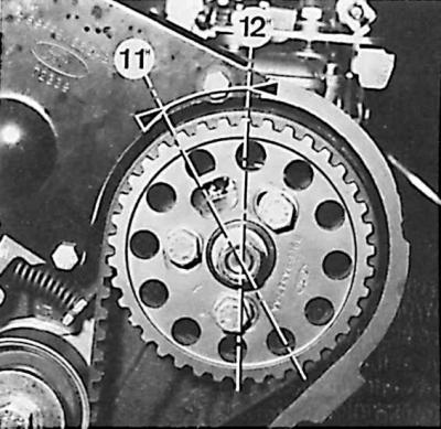
17. Rotate the crankshaft two full turns in the direction of its working rotation and set it in a position in which the cutout of the fuel pump pulley is at the 12 o'clock position.
18. Turn the crankshaft in the opposite direction and set the fuel pump pulley cutout to the 11 o'clock position.
19. Screw the mandrel into the inspection hole of the cylinder block to install the piston of the 1st cylinder at TDC and carefully rotate the engine crankshaft (in the direction of its working rotation) until it stops against the installation mandrel.
20. Insert the camshaft pulley installation tool into the hole provided for it (see Fig. Installing the valve timing system).
21. Loosen the bolts securing the middle pulley and tensioner roller by one turn; then push the section of toothed belt from the opposite side of the tensioner roller in its direction and release the belt.
22. Tighten all mounting bolts.
23. Remove all installation tools, then screw the plug into the inspection hole of the installation mandrel in the engine cylinder block.
24. Install the timing case cover.
25. Install and tension the alternator drive V-belt.
26. Install the coolant pump drive V-belt.
27. Connect the return oil line from the turbocharger to the engine cylinder block.
28. Screw on the front exhaust pipe.
29. Bolt the exhaust pipe bracket to the transmission crossmember.
30. Install new gaskets and connect the oil supply lines to the pump and turbocharger.
31. Connect the vacuum line bolted to the fuel pump to the intake manifold.
32. Check and, if necessary, adjust the valve clearance.
33. Install the cylinder head cover together with the gasket.
Then perform the remaining steps in the reverse order to the process of removing the cylinder head, paying attention to:
- maintaining the appropriate tightening torques for bolts and nuts;
- installing a new thermostat cover gasket;
- removing air from the fuel system;
- filling the cooling system and removing air from it;
- checking the tightness of all connections.
The original version can be found on the website (FORDBOOK.RU)