Valve clearance check
Valve clearance is checked with a feeler gauge between the back of the cam and the tappet.
1. Disconnect the crankcase breather hose from the cylinder head cover.
2. Remove cylinder block cover.
3. Turn the crankshaft of the engine by the pulley fastening nut (cannot be rotated by the camshaft pulley) in the direction of its working rotation to a position in which both cams of the 1st cylinder will be turned by the working part of the cam up.
4. Check the valve clearance of the 1st cylinder by inserting a feeler gauge plate between the back of the cam and the pushrod.
5. Determine the type of valve being tested (inlet or outlet) and compare the value of the measured gap with the required value (see subsection 3.2.1.2.2). If necessary, adjust the clearance of the valve being checked.
Attention! Valve installation sequence, counting from the front of the engine (from the drive side of the gas distribution system) in each cylinder is the same: the first (near the drive of the gas distribution system) is the intake valve and the other is the exhaust valve.
6. Repeat the described steps for the valves of the remaining cylinders in the injection sequence (1–3–4–2, counting from the side of the drives of the gas distribution system).
Valve clearance adjustment
Adjusting the valve clearance consists in replacing the adjusting plate located in the recess of the pusher. Replacing the adjusting plates does not require removing the camshaft if a special tool is used to perform this operation.
Attention! In the process of replacing the valve clearance adjustment plates, the engine pistons should not be exactly at TDC, but a few millimeters below (about 1/4 turn of the crankshaft). This will prevent the valve from hitting the bottom of the piston that is pressed when replacing the adjusting plate.
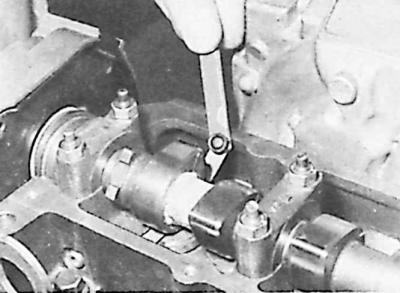
1. Rotate the tappets in such a way that, after compression, special pliers can be easily inserted into the cutouts in the bottoms of the pushers to remove the adjusting plates.
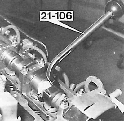
2. Set the engine crankshaft to the appropriate position (see description above) and with a pusher (tool 21.106) push down the pusher (simultaneously opening the valve and compressing its spring) so that with the help of special forceps (21.107) the adjustment plate could be removed.
3. Measure the thickness of the removed plate and, taking into account the measured clearance and the required nominal value, select from the kit a plate with a thickness that provides the required valve clearance.
4. Insert the matched plate in such a way that the surface with its designation is directed downwards (to the pusher).
5. Remove the pressure device.
6. Repeat the described operations for the remaining valves.
7. Install the cylinder head cover with a new gasket.
8. Attach the elastic pipe of the crankcase ventilation system to the cylinder head cover.
Visitor comments