Cylinder head
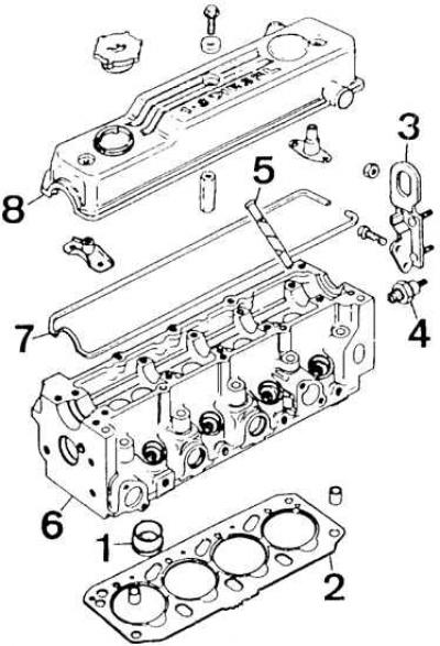
1 - vortex combustion chamber; 2 – laying of a head of the block of cylinders; 3 - bracket with an eye for lifting the engine; 4 - oil pressure sensor; 5 – vacuum pump drive rod; 6 – a head of the block of cylinders; 7 – laying of a cover of a head of the block of cylinders; 8 – a cover of a head of the block of cylinders
1. Disconnect ground wire from battery.
2. Drain the cooling system (see subsection 3.2.1.11).
3. Disconnect the air supply line to the turbocharger, the crankcase ventilation flex pipe from the cylinder head cover, and the air supply line between the air filter and the radiator shroud (the pipeline is put on the fitting).
4. Disconnect all elastic pipes of the cooling system from the cylinder head.
5. Disconnect the brake booster vacuum line and oil return line from the vacuum pump.
6. Disconnect the electrical wires from the glow plugs, oil pressure sensor, coolant temperature sensor, and radiator fan thermal switch.
7. Disconnect fuel return lines from injectors.
8. Disconnect injection lines from fuel pump and injectors.
9. Disconnect the thermostat cover from the cylinder head.
10. Disconnect fuel lines from pump and fuel filter.
11. Disconnect vacuum line from intake manifold.
12. Disconnect oil lines from turbocharger and oil pump.
13. Disconnect the turbocharger from the exhaust manifold.
14. Disconnect the bracket holding the front exhaust pipe from the transaxle cross member.
15. Disconnect the oil return line from the turbocharger and engine block.
16. Remove the water pump and alternator V-belts.
17. Unscrew the mounting bolt on the left side of the lower casing of the timing system drive.
18. Unscrew the bolt securing the upper casing of the timing system drive on the right side so that it can be removed.
19. Remove the three spring hooks of the upper casing of the timing system drive, remove the mounting bolts and lower the casing down.
20. Remove from the cylinder block, at the height of the crankshaft pulley, the plug of the control hole of the mandrel for installing the crankshaft.
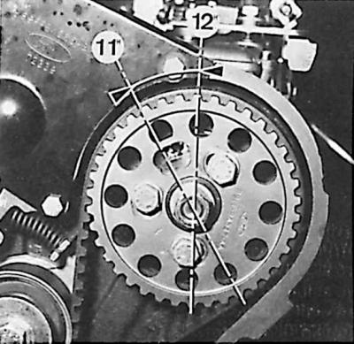
21. Rotate the crankshaft so that the notch of the fuel pump pulley is in position "12 hours".
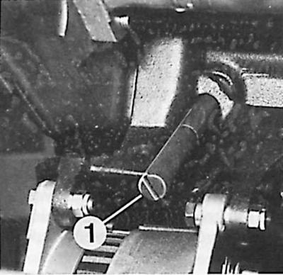
22. Install the mandrel in the cylinder block (1) for setting the crankshaft to the TDC position of the piston of the 1st cylinder.
23. Rotate the crankshaft counterclockwise until it stops against the mandrel.
24. Remove the timing belt tensioner pulley and then the timing belt.
25. Remove passive pulley (increasing angle of engagement of the toothed belt) and the rear cover of the gas distribution system drive.
26. Unscrew the nozzles.
27. Remove the cylinder head cover.
28. Unscrew the ten cylinder head bolts in reverse order to tightening them (see rice. Cylinder head bolt tightening sequence).
29. Remove the cylinder head.
Visitor comments