Crank mechanism
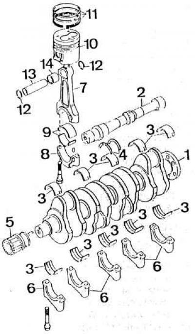
1 - crankshaft; 2 - intermediate shaft; 3 – liners of main bearings of a cranked shaft; 4 - thrust half rings of the crankshaft; 5 - pulley; 6 - caps of main bearings; 7 - connecting rod; 8 - connecting rod cover; 9 - liners of connecting rod bearings; 10 - piston; 11 - piston rings; 12 – a lock spring ring; 13 - piston pin; 14 - bushing of the connecting rod head
Crankshaft
The crankshaft is made of cast iron along with eight counterweights and is supported by five main bearings.
| Diameter of main journals: | |
| - nominal | 53.970 - 53.990 mm |
| - repair -0.25 | 53.720 - 53.740 mm |
| - repair -0.50 | 53.470 - 53.490 mm |
| Diameter of connecting rod journals: | |
| - nominal | 48.970 - 48.990 mm |
| - repair -0.25 | 48.720 - 48.740 mm |
| - repair -0.50 | 48.470 - 48.490 mm |
| Middle main bearing width: | |
| – nominal | 31.070 - 31.130 mm |
| – repair | 32.070 - 32.130 mm |
| Radial clearance of crankshaft main bearings | 0.015 - 0.062 mm |
| Axial clearance of the crankshaft | 0.093 - 0.306 mm |
| Maximum friction torque in the crankshaft main bearings (without installed piston-rod assemblies) | 10 Nm |
Main bearing shells
Inserts are thin. The manufacturer does not give the dimensions of the inserts.
Nominal and repair inserts are supplied as spare parts: reduced by 0.25 mm and 0.50 mm.
Connecting rods
Connecting rods are made with four distances between the axes of the holes of the head and the base to ensure one degree of compression in all engine cylinders. Notation "A", "IN", "WITH" And "D", applied on the side surface of the connecting rod caps, determine the selective group of the distance between the axes of the holes of the head and base.
Connecting rod installation method relative to cylinder block: letter "F", applied on the side surface of the connecting rod, must be located on the drive side of the gas distribution system.
Connecting rod bearing shell bore diameter: 52.000 - 52.020 mm.
The diameter of the hole in the bushing of the connecting rod head: 26.012-26.020 mm.
The distance between the axes of the holes of the head and the base of the connecting rod:
- group A: 129.880–129.940 mm;
- group B: 129.941–130.000 mm;
- group C: 130.011–130.060 mm;
- group D: 130.061–130.120 mm.
Connecting rod bearing shells
Thin wall liners. The manufacturer does not give the dimensions of the inserts. Nominal and repair inserts are supplied as spare parts: reduced by 0.25 mm and 0.50 mm.
Pistons
Light alloy pistons with a cast steel insert are used.
| Piston diameters (measured at right angles to the axis of the piston pin): | |
| - nominal: | |
| group A | 82.460 - 82.475 mm |
| group B | 82.475 - 82.490 mm |
| group C | 82.620 - 82.635 mm |
| group D | 82.635 – 82.650 mm |
| - repair: | |
| group E (0.5 mm) | 82.961 - 82.979 mm |
| group F (1.0 mm) | 83.461 - 83.479 mm |
| Piston clearance in cylinder: | |
| – groups A and D | 0.025 - 0.055 mm |
| – groups E and F | 0.021 - 0.054 mm |
| Protrusion at TDC of the piston bottom above the upper plane of the cylinder block | 0.50 - 0.84 mm |
Piston pins
The pin rotates in the piston and connecting rod head bushing (the so-called floating finger) and secured against longitudinal movement by two spring retaining rings.
Installation of circlips in the piston groove: cut upwards.
Pin outer diameter: 25.996–26.000 mm.
Piston rings
Each piston has three rings: two sealing and one oil scraper.
Installation Method: Lettering "Top" (top) directed towards the bottom of the piston.
Castle Width (incision) ring located in the cylinder:
- top ring (sealing): 0.35–0.50 mm;
- middle ring (sealing): 0.35–0.50 mm;
- bottom ring (oil scraper): 0.25–0.45 mm.
Piston groove clearance:
- top ring (sealing): 0.090–0.122 mm;
- middle ring (sealing): 0.050–0.082 mm;
- bottom ring (oil scraper): 0.030–0.065 mm.
Flywheel
Radial runout: 0.13 mm.
Number of crown teeth: 135.
Visitor comments