Gas distribution system
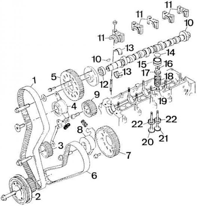
1 – a gear belt of a drive of system of gas distribution; 2 - crankshaft pulley; 3 - a pulley of an intermediate shaft; 4 – the tension device of a gear belt; 5 - camshaft pulley; 6 - drive toothed belt of the fuel pump; 7 – a pulley of the fuel pump; 8 - the tensioner of the drive toothed belt of the fuel pump; 9 - middle pulley; 10 - camshaft; 11 - camshaft bearing caps; 12 - sealing ring; 13 - camshaft bearing shells; 14 - valve clearance adjustment plate; 15 - pusher; 16 - crackers; 17 – a basic cup of a valve spring; 18 - valve spring; 19 - oil deflector cap; 20 - inlet valve; 21 - exhaust valve; 22 - valve seats
Attention! The contact surfaces of the cylinder block gasket and the head must be smooth, clean, without scratches or damage. Check the condition of the bottom surface of the cylinder head; this surface is not repairable (not regrindable). Before installing the head, make sure that the groove at the end of the camshaft eccentric is horizontal (parallel to the bottom plane of the cylinder head), and the larger part of the eccentric is directed upwards.
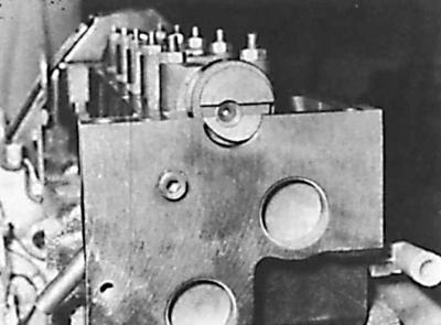
Places where the sealing paste is applied to the bearing cap No. 1 of the camshaft
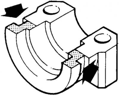
The places where the sealing paste is applied are shown by arrows.
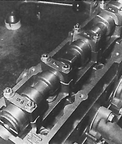
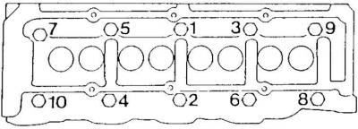
Designation of the installation direction and numbering of the camshaft bearing caps
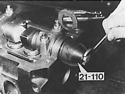
Installing the camshaft sealing ring using a special tool
The location of the camshaft groove when installing the cylinder head
Installation of a gas distribution system
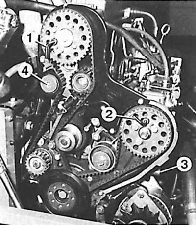
1 - a device for installing a camshaft; 2 – adaptation for installation of the fuel pump; 3 - a mandrel for installing the crankshaft in the TDC position; 4 - roller of the tensioner of the toothed belt of the drive of the gas distribution system
1. Measure the protrusion of the pistons above the upper plane of the cylinder block.
2. Depending on the protrusion of the pistons, select the appropriate thickness of the head gasket.
3. Install the head gasket on the cylinder block so that the side marked "TOP" was on top.
4. Install the head to the cylinder block.
5. Insert the mounting bolts into the corresponding holes in the cylinder head.
Attention! When installing the cylinder head, use new mounting bolts.
6. Tighten the cylinder head bolts to the correct torque in the correct sequence.
Attention! In later versions of the 1.8 dm3 engine, a different type of cylinder head bolts are used, which have M12 threads and Torx T70 heads. These bolts should be tightened in the same sequence as the old style bolts, with the following torques:
- 1 stage: 10 Nm;
- Stage 2: 100 Nm;
- Step 3: unscrew the bolt "1" 180°;
- Step 4: Tighten the bolt "1" torque 70 Nm;
- Step 5: Tighten the bolt "1" by an additional 120°.
- Step 6: Tighten as described above (steps 3–5) other bolts in the correct tightening sequence.
7. Screw the glow plugs into the cylinder head, tighten them to the correct torque, and connect the electrical wires.
8. Screw the injectors into the cylinder head, together with new thermal insulation washers, with the convex side towards the head.
9. Install the rear right casing of the timing system drive with the tensioner pulley.
10. Install rear left cowl with middle pulley. Check whether the rubber ring of the flexible pipe is in its place on the casing.
11. Install the camshaft pulley and insert the tool.
12. Check if the engine crankshaft touches mandrel 3 (see fig. Installation of a gas distribution system) at TDC position on cylinder 1.
13. Install a new timing belt for the timing system.
14. Tighten the timing belt for the timing system.
15. Remove all installation tools.
16. Tighten all mounting bolts.
17. Remove all installation tools, then screw the plug into the installation mandrel inspection hole in the engine block.
18. Install the timing cover.
19. Install and tension the alternator drive V-belt.
20. Install the water pump drive V-belt.
21. Screw on the front exhaust pipe.
22. Install new gaskets and connect oil lines to pump.
23. Connect the vacuum line screwed to the fuel pump to the intake manifold.
24. Check and, if necessary, adjust the valve clearance.
25. Install the cylinder head cover with gasket.
26. Then follow the rest of the steps in the reverse order of removing the cylinder head, paying attention to:
- compliance with the appropriate tightening torques for bolts and nuts;
- installing a new thermostat cover gasket;
- removal of air from the fuel system;
- filling the cooling system and removing air from it;
- checking the tightness of all connections.
Visitor comments