Contents: Checking the crankshaft and… ↳ Radial clearance ↳ Axial clearance ↳ Checking piston rings and piston… ↳
Crank mechanism
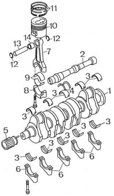
1 – crankshaft; 2 – intermediate shaft; 3 – crankshaft main bearing shells; 4 – crankshaft thrust half rings; 5 – pulley; 6 – main bearing caps; 7 – connecting rod; 8 – connecting rod cover; 9 – connecting rod bearing shells; 10 – piston; 11 – piston rings; 12 – retaining spring ring; 13 – piston pin; 14 – connecting rod head bushing
It is recommended to thoroughly clean and wash the parts that will be used again. Removing the plugs and caps from the cylinder block and cylinder head makes them much easier to clean. All gaskets and sealing rings should be replaced each time the engine is disassembled.
Checking the dimensions given in the technical specifications and comparing them with the actual values decides whether the part can be used further, repaired or replaced with a new one. The suitability of some parts is also indicated by the condition of their surface (scratches, cavities, etc.).
Checking the crankshaft and connecting rod clearances
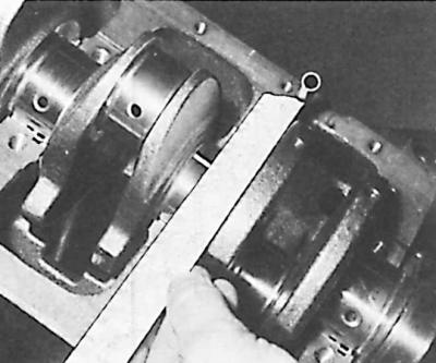
Measuring the deformation of the Plastigage measuring rod for determining the clearance in the crankshaft main bearing
Radial clearance
The radial clearance in the main and connecting rod bearings of the crankshaft is measured using special Plastigage measuring rods made of artificial material. The measuring rod, laid along the journal (main or connecting rod) and clamped in the bearing, is subjected to flattening. The radial clearance in the bearing can be determined (based on the appropriate scale on the packaging of the measuring rods) depending on the width of the deformed rod.
Measuring conditions with Plastigage measuring rods:
- the necks and liners must be dry and thoroughly degreased;
- the crankshaft must not change its position during the installation and removal of measuring rods;
- the measuring rod should be placed in half of the bearing shell, at a greater distance from the oil hole in the bearing shell or shaft journal;
- bearing caps must be installed by hand and their bolts must be tightened to the appropriate torque; do not hit the lids;
- only the bearing cap in which the radial clearance is measured should be tightened; it is not possible to measure clearances in all main bearings at the same time.
Crankshaft main bearing shell 1
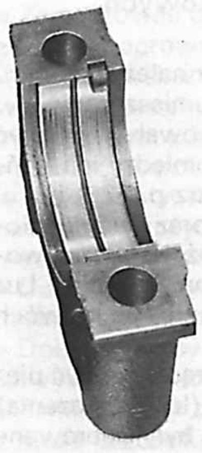
The liner of the 1 main bearing of the crankshaft is larger than the liners of the other bearings and has an oil groove.
1. Install the liners on the main bearings in the engine cylinder block and install the crankshaft into them.
Note! The shells of the first main bearing (on the timing drive side) are larger than the shells of the other bearings, and both have an oil groove. In the other bearings, the shells on the cylinder block side have an oil groove, and on the cover side have a smooth surface.
2. Place a Plastigage measuring rod on the first main journal.
3. Install the main bearing cap together with the liner and tighten the mounting bolts to the appropriate torque.
4. Carefully remove the bearing cap and measure the width of the deformed measuring rod using the scale supplied with the measuring rods. Determine the radial clearance in the bearing using the table or graph.
5. Compare the measured value with the required clearance value. If the measured clearance exceeds the permissible value, repair liners should be used.
6. Measure the clearance in the remaining main and connecting rod bearings in a similar manner.
Axial clearance
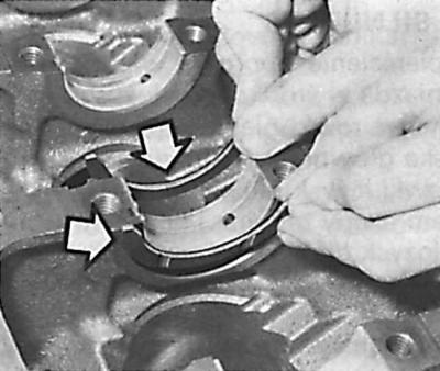
1. After installing the crankshaft in the cylinder block, install the crankshaft thrust half rings (the oil grooves should be directed outward from the main bearing), the bearing caps and tighten them to the appropriate torque.
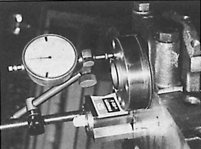
2. Place the dial indicator tip against the end of the crankshaft and measure its axial clearance.
3. Compare the measured values with the required values. If the gap exceeds the permissible value, then repair thrust half rings of correspondingly greater thickness should be used.
Checking piston rings and piston clearances in the cylinder
1. After removing the rings from the pistons, you should measure their clearance in the piston grooves, and after installing them in the cylinders in which they were previously installed, measure the width of the lock (gap) between their ends.
2. Measure the cylinder diameters and piston diameters (in the guide part, below the piston pin hole) at right angles to the piston pin axis. The piston clearance in the cylinder is equal to the difference between these two measurements.
3. Using a special device, install the rings on the pistons so that the inscriptions (or markings) are directed towards the bottom of the piston. Position the cuts in the rings at an angle of about 120°.
(The original can be found on this resource: FordBook)