Check all valve train components for damage and wear. Make sure that only original parts are installed and that all bolts and nuts are tightened to the specified torque.
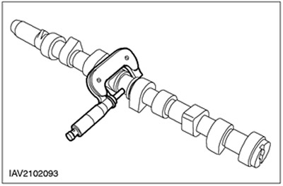
Camshaft journal diameter
1. Determine the diameters of the camshaft journals
- To determine if the journals are out-of-round, measure the diameter at 90 degree intervals using a micrometer.
- To determine if there is a taper, measure the diameter of each journal at two locations offset along the axis of the journal.
- If the measurements are not correct, install a new camshaft.
Radial clearance in the camshaft journal
1.
NOTE: Follow the prescribed procedure exactly. To perform the following measurements, the valve lifters must be removed.
NOTE: Make sure the camshaft type is correct (specification).
NOTE: Bearing caps and camshaft journals must be clean and free of oil.
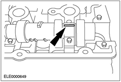
Position the thread of the tool for measuring radial clearances in plain bearings (Plastigage) on the bearing cover.
- Install the camshaft in the cylinder head without lubricating it.
- Lay a Plastigage clearance gauge thread equal in length to the width of the bearing cap on the corresponding journal.
2. Following the tightening sequence, install the camshaft bearing caps. Refer to the relevant Section 303-01.
3.
NOTE: Do not knock on bearing caps.
Remove bearing caps, refer to relevant Section 303-01.
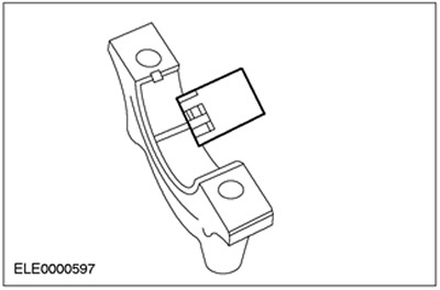
4. Using Plastigage, take a reading.
- Compare the width of the Plastigage thread with the appropriate scale.
- The scale reading corresponds to the radial clearance in the bearing.
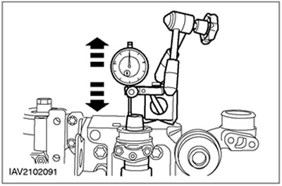
Camshaft axial clearance
1.
NOTE: Make sure the camshaft type is correct (specification).
Using a dial indicator, measure the end play.
- Move the camshaft in both directions. Take readings and record the maximum and minimum values.
- The axial clearance is equal to the difference between the maximum and minimum value.
- If the measurement result is out of specification, install new elements.
Inspection of the surface of the camshaft
1. Inspect the running surfaces of the camshaft lobes for pitting or damage. The presence of slight pitting outside the working surface is acceptable.
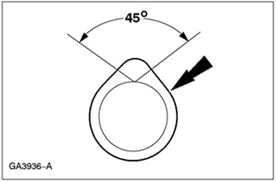
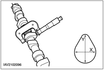
Camshaft lobe lift height
1. Determine the cam lift height.
- Using a micrometer, measure the length of the cam in both directions.
- The difference between the results of the two measurements is equal to the height of the cam.
Crankshaft journal diameter
General Equipment: Micrometer.
1. Measure the diameters of the main and connecting rod journals of the crankshaft.
- Repeat the measurement by moving the micrometer 90°to determine if there is any eccentricity.
- Measure the neck diameter at two different locations to determine if there is any taper.
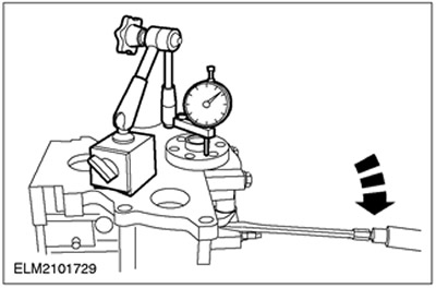
Axial clearance of the crankshaft
General Equipment
- Dial indicator
- Stand for dial indicator
1.
NOTE: Operation only for vehicles with Zetec-E engine. On Zetec-SE engines, disassembly of the crank mechanism is not allowed.
Determine the axial clearance.
- Set up the dial indicator and tripod.
- Determine the end play by lifting the crankshaft with a screwdriver.
- If necessary, adjust the axial clearance using new thrust washers.
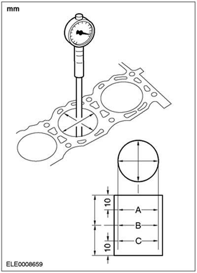
Cylinder bore taper
1.
NOTE: Main bearing caps must be in place and torqued to specification. However, bearing shells must not be installed.
Measure the cylinder diameter using an outside micrometer.
- To determine if there is any deviation in the shape of the cylinder from roundness or taper, take measurements in different directions and at different heights.
- If the measurement is not correct, install a new cylinder block or honing the cylinder block (if applicable/allowed).
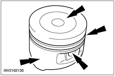
Piston Inspection
1.
CAUTION: Do not use aggressive cleaning fluid or a wire brush to clean the piston.
Perform a visual inspection.
- Clean the piston skirt, piston pin bushing, grooves and piston head and inspect them for wear and cracks.
- If there are signs of wear on the piston skirt, check that the connecting rod is not deformed or twisted.
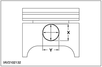
Correspondence of the piston pin and the bore in the piston
1.
NOTE: Piston and piston pin form a single pair. Do not confuse these elements.
Measure the diameter of the piston pin bore.
- The measurement should be carried out in two directions.
- If the values are out of specification, install a new piston and a new piston pin.
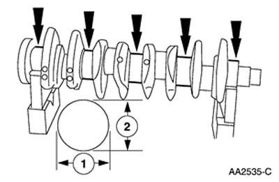
Piston diameter
General Equipment: Micrometer.
1.
NOTE: Mark the piston to ensure proper piston installation.
Using a micrometer, measure the piston diameter.
Piston ring gap
1.
CAUTION: Do not confuse piston rings. Piston rings should be installed in the same position and in the same places.
Take the piston ring and use the ringless piston to push the piston ring into the cylinder approximately 30mm.
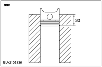
2. Using a set of feeler gauges, measure the clearance at the piston ring joint.
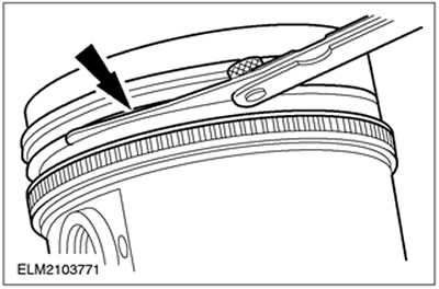
Gap between groove and piston ring
General equipment: Set of probes.
1.
NOTE: The piston ring must protrude from the piston groove. To determine the height gap between the groove and the ring, insert the feeler gauge directly into the groove behind the ring.
Using a feeler gauge set, measure the height clearance between the groove and the ring.
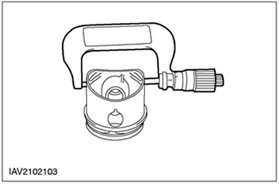
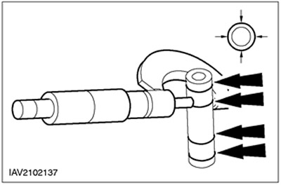
Piston pin diameter
1.
NOTE: Piston and piston pin form a single pair. Do not confuse these elements.
Measure the piston pin diameter.
- Measure in two directions
- If the values are out of specification, install a new piston and a new piston pin.
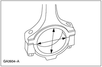
Connecting rod hole
1. Measure the connecting rod head bore diameter at two locations. The difference in the measurement results is the deviation of the shape of the circle of the hole from roundness. Check diameter and roundness for specification.
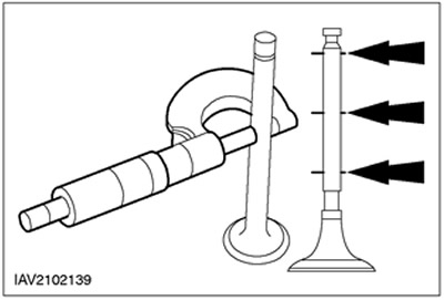
Valve stem diameter
1. Use a micrometer to measure the valve stem diameters. If the measurement result is not correct, install a new valve.
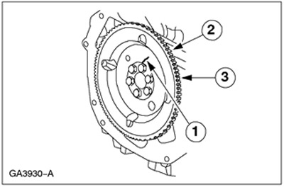
Flywheel inspection
1. Inspect the flywheel for:
- 1. Presence of cracks
- 2. Wear of the ring gear
- 3. The presence of chips and cracks on the ring gear
Deformation (warpage) mating surface of the cylinder head
General equipment:
- Probe set
- Straight ruler
1.
CAUTION: The mating surface on 2.5L engines should not be reworked.
Using a straightedge and feeler gauge, measure the distortion of the cylinder head mating surface.
- Measure the shape distortion of the mating surface.
- If the value is out of specification, rework the mating surface.
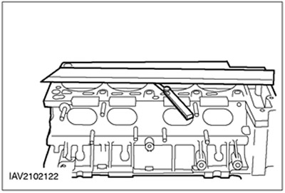
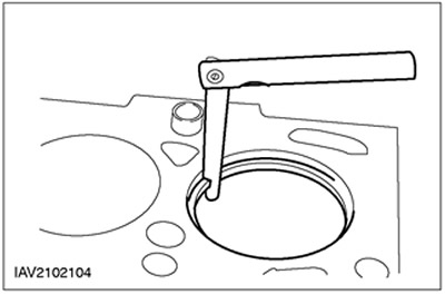
Deformation (warpage) mating surface of the cylinder block
1. Using a straightedge and a set of feeler gauges, measure the flatness of the cylinder block/cylinder head mating surface.
- Measure the flatness deviation of the mating surface.
- If measurement results are out of specification, refinish the mating surface (if allowed).
Cleaning and inspection of the exhaust manifold
1. Inspect the exhaust manifold flanges that mate to the cylinder head for signs of exhaust gas leakage.
2. Inspect the exhaust manifold for cracks, damage to gasket surfaces, or other damage that could render the manifold unusable.
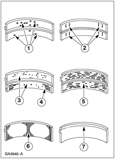
Bearing inspection
1. Inspect the bearings for the following defects.
- 1. Chipping (well formation) - fatigue wear
- 2. Polished in places - incorrect fit
- 3. Inclusions - dirty engine oil
- 4. Scratches - dirty engine oil
- 5. Seizures - poor lubrication
- 6. Wear on both edges - neck damage
- 7. One lip wear - neck taper or improper fit
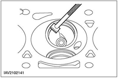
Valve seat inspection
General equipment: Ruler for measuring valve seat width.
1. Measure the width of the valve seat.
- Measure the width of the valve seat; for this, a ruler is used to measure the width of the valve seat.
- If the measurement is out of specification, rework the valve seat.
Visitor comments