NOTE: Powertrain Control Module (RSM) receives an error message if the relay is removed or the electrical components are disconnected. This error message must be cleared from the fault memory after measurements have been taken by connecting the WDS system.
NOTE: Valve clearances must be properly adjusted before performing a compression test. Make sure the engine is at normal operating temperature.
NOTE: Different designs of compression testers and fluctuation in starter speed will usually only verify that compression is the same in all cylinders.
Compression pressure test (engine 1.4/1.6 Zetec - SE)
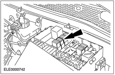
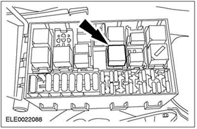
1. Open the central electrical box (CJB) and remove the fuel pump relay.
NOTE: The engine will start, run for a few seconds and then stall.
2. Start the engine: the engine will start, run for a few seconds and then stall.
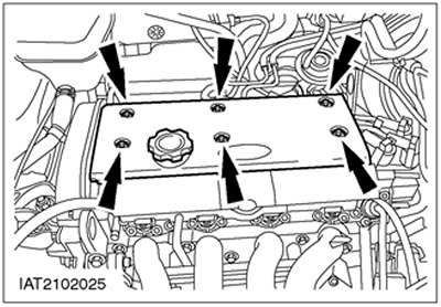
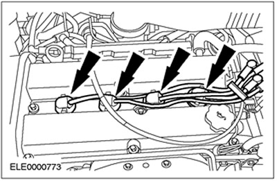
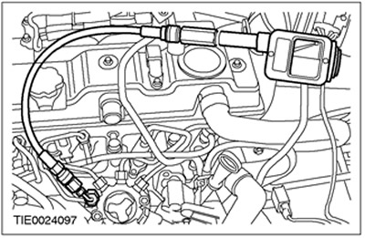
3. Remove the spark plug cover from the valve cover.
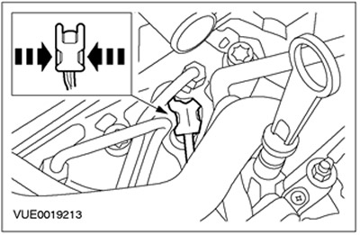
NOTE: When disconnecting the elements, pull on the connector, not on the wire. Disconnect the spark plug connector and remove the spark plugs.
4. Disconnect the spark plug connectors.
5. Disconnect the ignition coil connector.
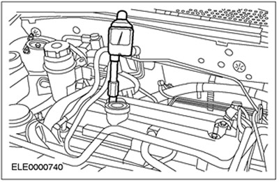
6. Using the special tool, remove the spark plugs.
NOTE: Run the starter at wide open throttle until the needle on the gauge stops moving up.
7. Perform a measurement on each cylinder using the appropriate compression pressure recorder and following the instructions supplied with the meter.
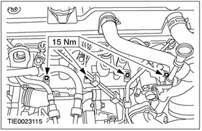
8. Reinstall the elements, working in reverse order and observing the specified tightening torques. Apply silicone grease to the spark plug connector seal before installing (A960-M1C-AA). Apply lubricant to the threads of the spark plugs (ESE-M1244-A). Valve cover tightening torque: 6 Nm. Spark plug tightening torque: 15 Nm.
9. Reconfigure the PCM memory, which stores information about faults.
Compression pressure measurement (Zetec-E engine)
1. Open the central electrical box (CJB) and remove the fuel pump relay.
NOTE: The engine will start, run for a few seconds and then stall.
2. Start the engine: the engine will start, run for a few seconds and then stall.
NOTE: Turn the spark plug connector slightly before disconnecting it. When disconnecting the elements, pull on the connector, not on the wire.
3. Disconnect the spark plug connectors and remove the spark plugs.
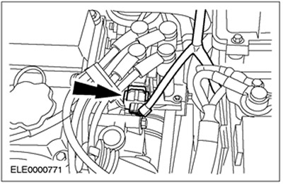
4. Disconnect the plug connector of the ignition coil (EI).
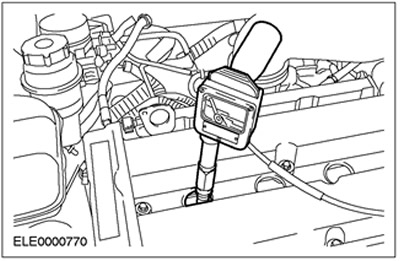
NOTE: Perform the required measurement on each cylinder using compression pressure recorder 623.000.101.
5. Take a measurement on each cylinder using the appropriate compression pressure recorder.
6. Reinstall the elements, working in reverse order and observing the specified tightening torques. Apply silicone grease to the spark plug connector seal before installing (A960-M1C-AA). Apply lubricant to the threads of the spark plugs (ESE-M1244-A). Valve cover tightening torque: 1st stage: 2 Nm; 2nd stage: 7 Nm. Spark plug tightening torque: 15 Nm.
7. Reconfigure the PCM memory, which stores information about faults.
Compression pressure measurement (Endura DI engine)
WARNING: Do not smoke or allow lit cigarettes or any open flame to be present when working on or near any fuel-containing elements. In such situations, there are always highly flammable mixtures that can ignite. Failure to follow these instructions may result in injury.

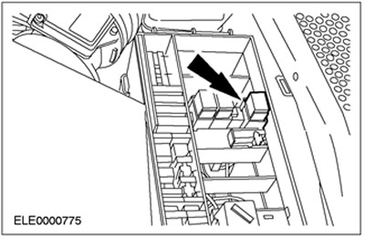
1. Open the central electrical box (CJB) and remove the glow plug relay.

2. Remove the engine top cover.
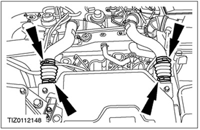
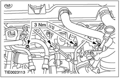
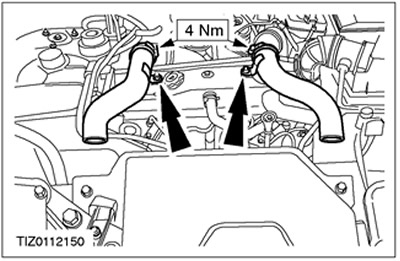
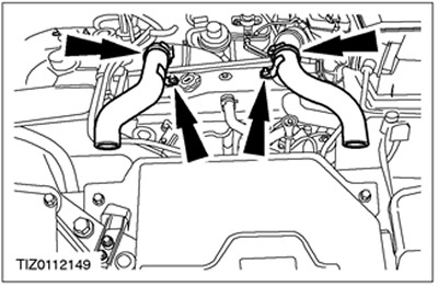
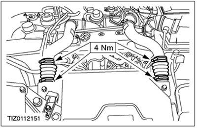
3. Remove the charge air cooler inlet and outlet hoses and clamps.

4. Remove the intake and exhaust pipes of the charge air cooler.
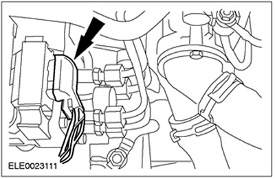
5. Disconnect the high pressure fuel pump connector.
6. Remove the power supply leading to the glow plugs.

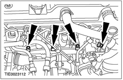
7. Remove glow plugs.
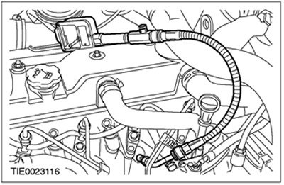
8. Install an appropriate compression tester with the appropriate adapter in the glow plug hole.
NOTE: Crank the engine over with the starter until the compression gauge reading stops rising.
9. Measure all cylinders following the instrument manufacturer's instructions.
10. Disconnect the compression tester and adapter.
11. Install glow plugs.
12. Install the power supply to the glow plugs.

13. Connect the high pressure fuel pump connector.
14. Install the charge air cooler inlet and outlet pipes.

NOTE: Set the worm-drive clamps to the «8 ocloc'k» when viewed from the front of the car.
15. Install the charge air cooler inlet and outlet hoses and clamps.

16. Install the engine top cover.

17. Install the glow plug relay.
18. Reconfigure the PCM memory containing information about malfunctions.
Measurement of compression pressure (Duratorq TDCi engine)
WARNING: Do not smoke or allow lit cigarettes or any open flame to be present when working on or near any fuel-containing elements. In such situations, there are always highly flammable mixtures that can ignite. Failure to follow these instructions may result in injury.
WARNING: Do not make any repairs to the fuel injection system without checking that the fuel pressure has dropped to zero and the fuel temperature has reached the outside temperature or below 30°C, whichever is greater. Failure to follow these instructions may result in injury.
1. Using the function «Data logger» («Datalogger») world diagnostic system (WDS), check that the fuel pressure has dropped to zero and the fuel temperature has reached the outside temperature or a temperature below 30°C, whichever is greater.

2. Open the central electrical box (CJB) and remove the glow plug relay.

3. Remove the engine top cover.

4. Remove the charge air cooler inlet and outlet hoses and clamps.
5. Remove the inlet and outlet pipes of the charge air cooler.
CAUTION: Do not disconnect the high pressure fuel pump connectors and crank the engine.
6. Disconnect the fuel injector connectors.

7. Remove the power supply leading to the glow plugs.

8. Remove glow plugs.
9. Install an appropriate compression tester with the appropriate adapter in the glow plug hole.
NOTE: Crank the engine over with the starter until the compression gauge reading stops rising.
10. Measure all cylinders following the instrument manufacturer's instructions.
11. Disconnect the compression tester and adapter.

12. Install glow plugs.

13. Install the power supply to the glow plugs.

14. Connect the fuel injector connectors.

15. Install the charge air cooler inlet and outlet pipes.
NOTE: Set the worm clamps to the position «8 ocloc'k» when viewed from the front of the car.
16. Install the charge air cooler inlet and outlet hoses and clamps.
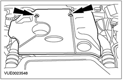
17. Install the engine top cover.
18. Install the glow plug relay.
19. Reconfigure the PCM memory containing information about malfunctions.
Visitor comments