Special tool
 | O-ring remover 100-010 (17-063) |
 | Adapter 205-071-02 (15-026-51) |
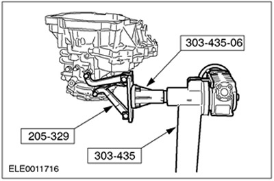
 | Engine/Differential Mounting Bracket 205-329 (15105A) |
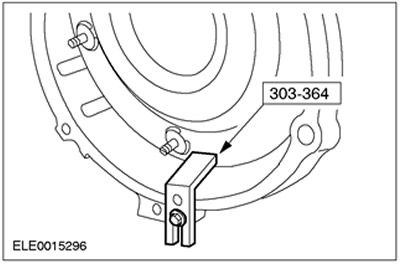
 | Valve Spring Compressor 303-364 (21-158) |
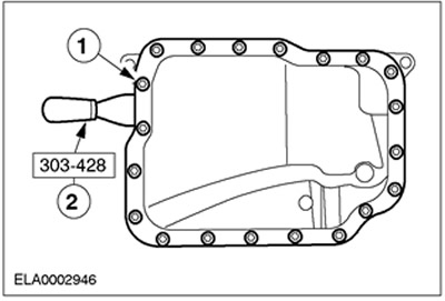
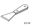 | Oil pan puller 303-428 (21-179) |
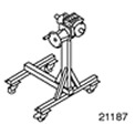 | Booth 303-435 (21-187) |
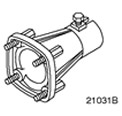 | Support bracket for 303-435 303-435-06 (21031B) |
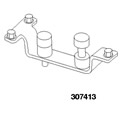 | Final Drive Pinion Holding Tool 307-413 (17-079) |
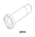 | Socket wrench for main gear pinion nut 307-414 (17-080) |
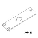 | Plate spanner 307-420 (17-085) |
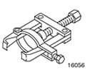 | Secondary Shaft Needle Roller Bearing Bushing Puller 308-191 (16-056) |
| Name | Specification |
| Automatic transmission fluid | WSS-M2C202-B |
| Metal Surface Cleaner | WSE-M5B392-A |
| Screw | M10 x 1.25 |
1.
CAUTION: If abrasive particles (clutch disc particles, metal shavings, or foreign material) are found in the transaxle fluid during repair, the transaxle must be completely disassembled and cleaned. The lines, transmission fluid cooler, and torque converter must also be thoroughly cleaned. If the lines are severely contaminated, install a new transmission fluid cooler and torque converter.
NOTE: If the clutch is worn, flush the torque converter with clean transmission fluid or equivalent that meets Ford specification.
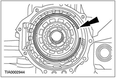
During disassembly, inspect the gearbox in the block with the drive axle.
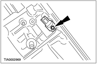
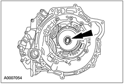
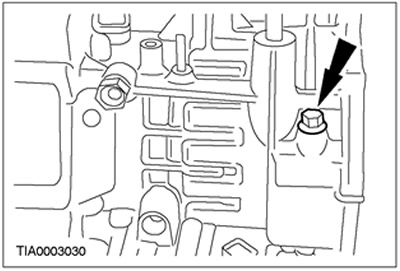
2. Remove the secondary shaft speed sensor (OSS).
3. Remove the turbine shaft speed sensor (TSS).
4.
CAUTION: Do not use air tools.
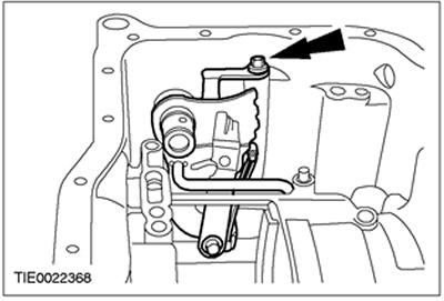
While holding the lever, remove the manual control lever.
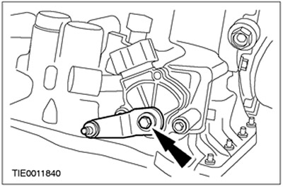
5. Remove the transmission range (TR) sensor.
6. Remove the special tool.
7.
CAUTION: To avoid damaging the torque converter hub, do not tilt the torque converter when removing it.
NOTE: The torque converter is filled with transmission fluid. Drain the transmission fluid into a suitable container.
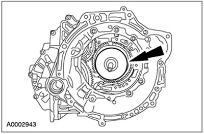
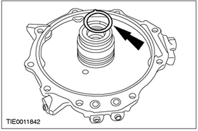
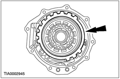
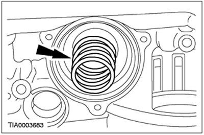
Remove the torque converter.
8. Using a special tool, secure the gearbox in the block with the drive axle.
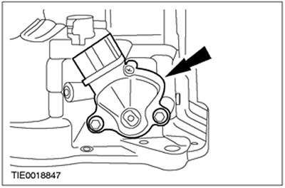
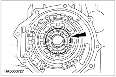
9. Unscrew the working fluid pump bolts.
10. Remove the pump. Install two M10x1.25 bolts into the pump and remove it.
11. Remove the pump seals.
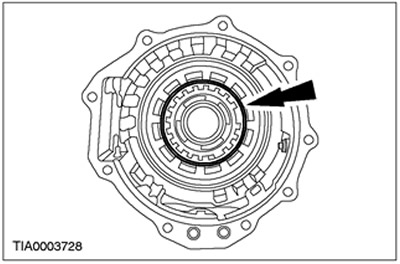
12. Remove the forward clutch thrust washer.
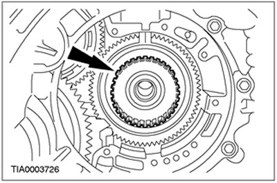
13. Remove the forward clutch assembly.
14.
NOTE: Small levers will assist in removing the forward clutch hub.
Remove the forward clutch hub.
15. Turn the gearbox in the block with the drive axle by 180 degrees.
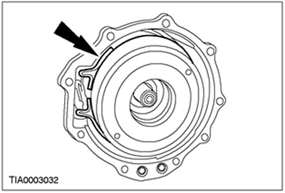
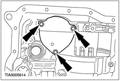
16. Remove the end cover.
17. Thoroughly remove silicone sealant from the surfaces of the transmission fluid case and transaxle case using metal cleaner or equivalent that meets Ford specification.
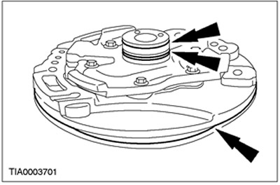
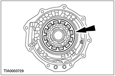
18. Remove the direct drive clutch hub bearing adjusting shim.
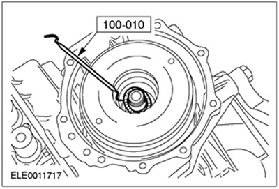
19. Using the special tool, remove the end cover seals.
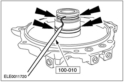
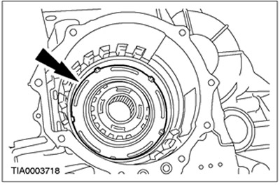
20. Remove the seals located between the end cover and the crankcase.
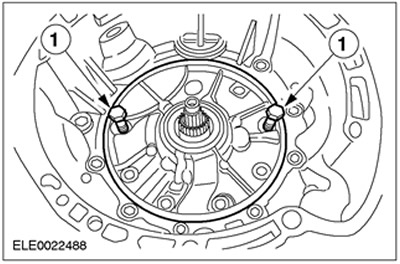
21. Using the special tool, remove the direct clutch cylinder thrust bearing.
22. Remove the intermediate and overdrive band brake anchor bolt.
23. Remove the intermediate and overdrive band brake.
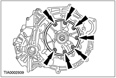
24. Remove the intermediate and overdrive band brake drum assembly.
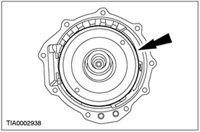
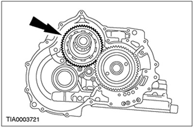
25. Remove the planetary gear assembly.
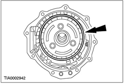
26. Remove the retaining ring of the low and reverse clutch discs.
27. Remove the discs, pressure plate and beveled ring of the low and reverse clutch.
28. Remove the low gear one-way clutch retaining ring.
29. Remove the inner race of the low gear one-way clutch.
30. Remove the low and reverse clutch return spring.
31. Remove the low and reverse clutch piston.
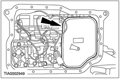
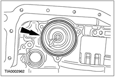
32. Remove the transmission fluid pan and drain the fluid using a suitable drain pan.
- 1. Remove the bolts.
- 2. Using the special tool, separate the transmission fluid pan from the transaxle.
33. Thoroughly remove silicone sealant from the surfaces of the transmission fluid case and transaxle case using metal cleaner or equivalent that meets Ford specification.
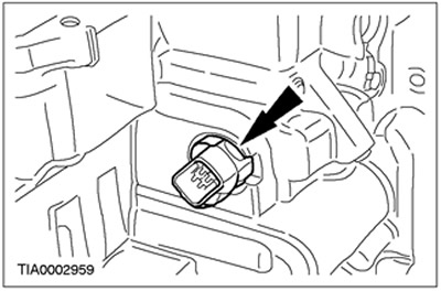
34. Remove the transmission fluid temperature (TFT) sensor.
35. Remove the transmission fluid filter.
36.
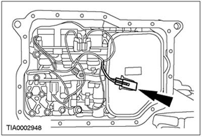
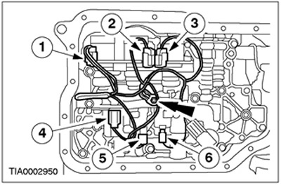
NOTE: It is important to note the positions of the main control unit wiring harness connectors as they can only be connected in the same positions. The connector color letters are molded into the solenoid valve block.
Remove the ground wire bolt. Disconnect the plug connectors and remove the wiring harness.
- 1. SSC solenoid valve; Color W (white)
- 2. SSE Solenoid Valve: Color G (Green)
- 3. SSD Solenoid Valve: Color L (Blue)
- 4. EPC Solenoid Valve: Color B (Black)
- 5. SSA solenoid valve: Color N (neutral (grayish))
- 6. SSB Solenoid Valve: Color B (Black)
37.
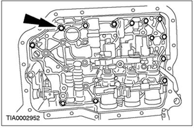
NOTE: Note the location of the longer bolts.
Remove 13 bolts securing the main control valve block.
38.
NOTE: Squeeze the locking elements on the connector.
Remove the internal transaxle wiring harness connector.
39.
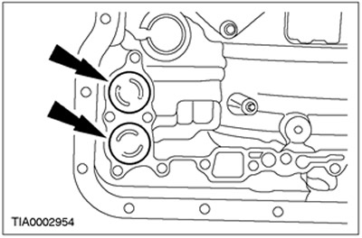
NOTE: Each of these two accumulators has two springs. All four springs are different sizes.
NOTE: For subsequent assembly, mark the size and location of the accumulator springs.
Remove the accumulator pistons and springs.
40. Remove the cylindrical pin from the hand lever.
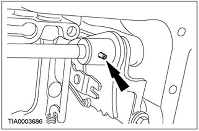
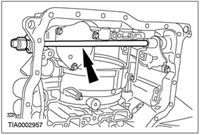
41. Remove the hand lever shaft.
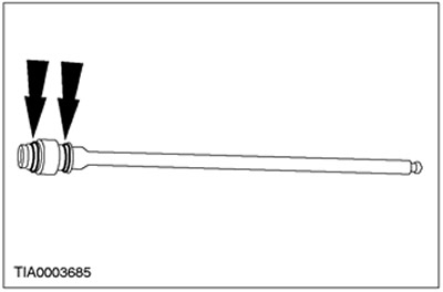
42. Remove the O-rings from the hand lever shaft.
43. Remove the control lever assembly.
44.
CAUTION: The idler/overdrive band brake servo unit cover is spring loaded. The bolts should be turned out evenly until the plate is relieved, then completely removed.
Remove the cover of the intermediate and overdrive band brake servo unit.
- Remove the bolts.
- Remove the cover of the intermediate and overdrive band brake servo unit.
45. Remove the O-ring.
46. Remove the intermediate and overdrive band brake servo unit piston.
47. Remove the return spring of the intermediate and overdrive band brake servo unit piston.
48. Turn the gearbox in the block with the drive axle by 180 degrees.
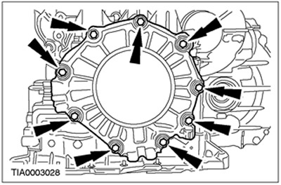
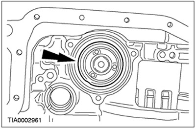
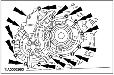
49. Remove the bolts and separate the torque converter housing from the gearbox housing in the block with the drive axle.
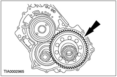
50. Remove the differential assembly.
51. Remove the parking latch cover assembly.
52. Remove the parking latch support.
- 1. Disconnect the spring.
- 2. Remove the pin.
- 3. Remove the lever.
- 4. Remove the parking latch support.
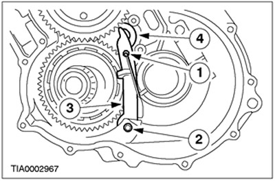
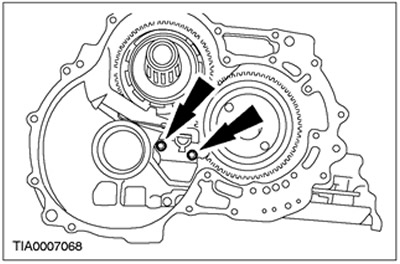
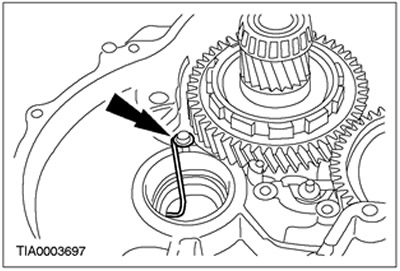
53. Remove the spring.
54. Remove the pinion shaft gear.
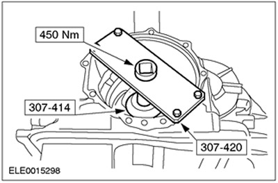
55. Using the special tool, lock the main gear pinion.
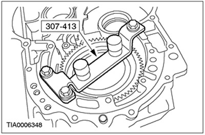
56. Turn the gearbox in the block with the drive axle by 180 degrees.
57.
NOTE: Move the locking sleeve away from the final drive pinion bearing retaining nut.
Using a special tool, remove the main gear pinion bearing mounting nut.
58. Turn the gearbox in the block with the drive axle by 180 degrees.
59. Remove the special tool.

60.
CAUTION: When removing the bearing, support the final drive pinion to prevent it from falling out of the transaxle housing.
Rotate the gearbox in the block with the drive axle by 180 degrees.
61. Remove the main gear pinion bearing by lightly tapping the end of the main gear pinion. Remove the main gear pinion.
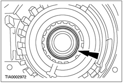
62. Remove the deformable washer and discard it as no longer needed.
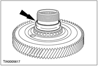
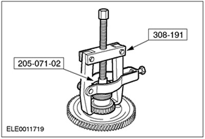
63. Using the special tool, remove the main gear pinion bearing.
64. Thoroughly clean the surfaces of the torque converter housing and transaxle housing using a metal cleaner or equivalent that meets Ford specification.
The original article is posted at: FORDBOOK.ru