Examination
1. To check the operation of the servo amplifier, press the foot brake pedal several times to eliminate the vacuum. Then start the engine, holding the pedal down. When the engine starts, you will feel the pedal "pull" as the vacuum increases. After the engine has been running for some time (at least a couple of minutes), turn it off. Now, when you press the pedal, you will hear a whistling sound coming from the servo amplifier. After four or five presses, this sound should stop, and the pedal should become "harder".
2. If the servo amplifier does not work as described above, then first of all you need to check the servo amplifier check valve (see paragraph 12).
Removal
Models with 4-cylinder engines
3. Remove the master cylinder (paragraph 11).
4. Remove the air cleaner and intake duct (chapter 4A).
5. On models with air conditioning, remove the bolts of the refrigerant pipe brackets near the servo booster and move the brackets to the side.
6. Disconnect the vacuum hose adapter from the servo booster by pulling it out of the rubber bushing. If it is difficult to pull out, use a screwdriver to pry it under the flange.
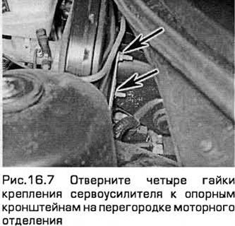
7. Unscrew the four nuts securing the servo amplifier to the support brackets on the engine compartment bulkhead (see Fig. 16.7).
8. On right-hand drive models, slide the servo until its studs are clear of the brackets. Have an assistant hold the brake pedal down. Then pull out the elastic retainer and remove the pin (which held the retainer) securing the servo pushrod to the pedal link arm.
9. On left-hand drive models, remove the nut that secures the pedal pin to the servo pushrod inside the passenger compartment. This nut is located near the top of the pedal and can be removed through a special access hole.
10. For better access, first remove the bottom panel from the front panel.
11. Remove the servo amplifier from the bulkhead and remove it from the engine compartment.
12. On left-hand drive models, be careful not to damage the rubber bulkhead bushing when you pull the pushrod through it.
13. Please note that the servo amplifier cannot be repaired and in case of malfunction it must be replaced.
Models with V-shaped 6-cylinder engines
14. Disconnect the accelerator and cruise control cables from the throttle body (chapter 4A).
15. On models with automatic transmission, remove the two bolts securing the transmission gear selector cable bracket. Disconnect the cable end and move the cable to the side.
16. Disconnect the motor wiring connector (if not already done) located in front of the servo amplifier assembly.
17. Disconnect the fuel injection and drain lines from the fuel rail (chapter 4A).
18. Disconnect the main wire from the starter (chapter 5A).
19. Remove the servo from the bulkhead and remove it from the engine compartment. On left-hand drive models, be careful not to damage the bulkhead rubber grommet when you pull the pushrod through it.
20. Please note that the servo amplifier cannot be repaired and in case of malfunction it must be replaced.
Installation
21. Installation - in the reverse order of removal. When removing the master cylinder, see. paragraph 11.