Contents: Removal ↳ Installation ↳
Warning: Brake fluid is dangerous. If it comes into contact with your skin, rinse it off immediately and thoroughly. If it gets into your eyes, seek medical attention. Brake fluid will damage paint and plastic. If it comes into contact with such surfaces, rinse it off immediately and thoroughly with clean water.
Removal
1. Create a vacuum in the servo by pressing the brake pedal several times (engine not running).
2. On models with automatic transmission, remove the transmission fluid dipstick for better access.
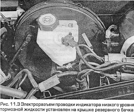
3. Disconnect the low brake fluid indicator wiring harness electrical connector. This electrical connector is installed on the reserve tank cap (see Fig. 11.3). Unscrew and remove the cap.
4. Pump the liquid out of the tank using a tube.
Warning: Do not suck out the fluid through the tube with your mouth, it is dangerous. If brake fluid gets on the paintwork, it must be washed off immediately with clean water.
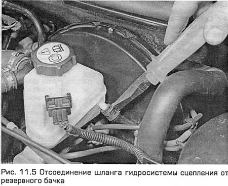
5. On models with a hydraulic clutch, loosen the hose clamp and disconnect it from the reserve tank (see Fig. 11.5). Plug the hose to prevent dirt from getting into it.
6. Locate the location of each brake line on the master cylinder. On models without ABS, there are four lines. The two rear brake lines are connected to the pressure limiting valves mounted on the master cylinder. On models equipped with ABS, the master cylinder has only two lines connecting it to the ABS hydraulic modulator (see Fig. 11.6).
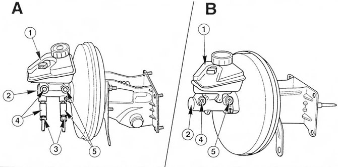 Fig. 11.6. Master cylinder connections (A - models without ABS, B - models with ABS).
1. Reserve tank
2. Master cylinder
3. Pressure limiting valves for rear brakes
4. Primary circuit of the brake hydraulic system (front right/rear left brake)
5. Secondary circuit of the brake hydraulic system (front left / rear right brake)
7. Place rags around the master cylinder to catch any drips.
8. Wipe off the union nuts. Unscrew the nuts and disconnect the pipes from the master cylinder.
9. Remove the cylinder mounting nuts and lift the cylinder off the studs mounted at the front of the brake booster. If the nuts are difficult to remove, use a socket wrench instead of a regular spanner. Plug or cover the resulting openings to prevent dust or dirt from getting in.
10. Remove the gasket from the master cylinder.
11. If the master cylinder is faulty, it must be replaced. At the time of writing, repair kits for it were not available.
Installation
12. Clean the mating surfaces of the master cylinder and servo booster. Install a new gasket on the master cylinder.
13. Install the master cylinder onto the servo studs. Install and tighten the nuts to the specified torque.
14. Carefully insert the pipes into the master cylinder holes, and then tighten the nuts. Make sure that the nuts enter the threads without distortion.
15. Install the clutch hydraulic hose (if equipped).
16. Remove air from the brake hydraulic system (paragraph 15) and clutches (if any) (paragraph 6).
17. Install the reservoir cap and connect the low brake fluid indicator electrical connector.
18. On models with automatic transmission, install the transmission fluid dipstick.
19. Before resuming driving, thoroughly check the brakes.
[The original post is on the web portal: FORDBOOK.ru]