Contents: Removal and installation the gearbox ↳ Removal and installation the gear… ↳ Adjusting the kick-down mechanism… ↳ Adjusting the kick-down mechanism… ↳ Adjusting the front planetary gear… ↳ Checking the oil level ↳
Adjusting the kick-down mechanism cable in version 1
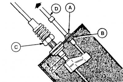
X = 8 mm – control dimension A – kick-down mechanism cable tension adjustment nut, B – lock nut, C – accelerator pedal cable tension adjustment nut, D – cable casing
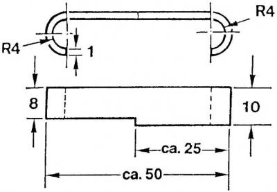
Dimensions of the template for adjusting the kick-down mechanism cable
Adjusting the kick-down mechanism cable in the 2nd version
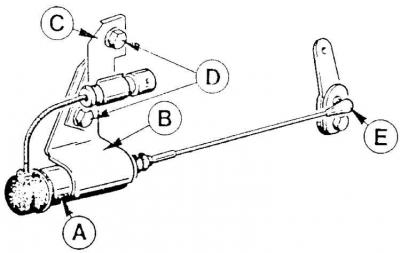
A – electromagnetic valve, B – housing, C – holder, D – mounting bolt, E – ball pin of cable connection
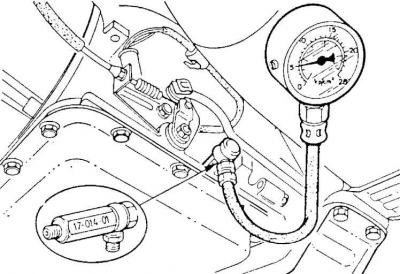
Checking the oil pressure in an automatic transmission
Removal and installation the gearbox
The method of removing and installing the gearbox is given in subsection 6.3.9.
Removal and installation the gear reduction cable (rick-down mechanism)
The method for removing and installing the gear reduction cable is given in subsection 6.3.10.
Adjusting the kick-down mechanism cable (version 1)
1. Loosen the nut (A) (see Fig. Adjusting the kick-down mechanism cable in version 1) for adjusting the tension of the kick-down mechanism cable and its lock nut (B).
2. Move the nut and locknut to the end of the thread.
3. Press the accelerator pedal all the way down and lock it in this position.
4. Turn the nut (C) for adjusting the tension of the accelerator pedal cable until the dimension X = 10 mm is obtained (see Fig. Adjusting the kick-down mechanism cable in the 1st version).
5. To check the size (X), it is recommended to use a template according to Fig. Dimensions of the template for adjusting the kick-down mechanism cable.
6. During the rotation of the nut (C), the spring and sleeve supported by it cannot rotate, as this would cause a change in dimension (X) during the movement of the vehicle.
7. After adjustment, remove the template.
8. Between the elements for which the size (X) is determined, place the second side of the template in accordance with Fig. Dimensions of the template for adjusting the kick-down mechanism cable (8 mm wide) and release the accelerator pedal. The template should remain clamped by these elements.
9. Pull the kick-down cable housing (D) by hand in the direction shown by the arrow (see Fig. Adjusting the kick-down cable in version 1) to eliminate play in the cable and hold the housing in this position.
10. Screw the adjusting nut (A) until it stops against the casing plate, and then tighten its lock nut (B).
Adjusting the kick-down mechanism cable (2nd version)
1. With the gear shift lever in any position, turn on the ignition and press the accelerator pedal all the way down.
2. Hold the pedal in this position.
Warning! Do not start the engine.
3. Turn the kick-down lever in the gearbox counterclockwise until it stops.
4. Move the solenoid valve forward until its cable is slightly taut.
5. First tighten the lower of the two mounting bolts (D) (see Fig. Adjusting the kick-down cable in the 2nd version) to secure the solenoid valve, and then tighten the upper bolt; both bolts are tightened to a torque of 29–41 Nm.
6. Release the accelerator pedal.
7. Check the adjustment - the kick-down lever should be able to turn counter-clockwise until it stops when the accelerator pedal is pressed all the way and the ignition is on. The control cable should be slightly taut.
Adjusting the front planetary gear brake band
The method for adjusting the front planetary gear brake band is given in subsection 6.3.8.
Checking the oil level
The method for checking the oil level in an automatic transmission is given in subsection 6.3.3.
Checking oil pressure during gearbox operation
1. Connect the pressure gauge to the hole in the crankcase (see Fig. Checking the oil pressure in the automatic transmission) after removing the plug.
2. Warm up the transmission to operating temperature. Measure the oil pressure with the engine idling (for correct values, see subsection 6.3.1).
3. If the oil pressure is too low, check the oil level and the tightness of the hydraulic control unit housing, the hydrokinetic transmission housing and the oil pump.
4. If the oil pressure is too high, you should check the idle speed, the tightness of the vacuum line of the gearbox regulator and its connection to the engine fuel system, the vacuum regulator of the gearbox and the hydraulic control unit in the gearbox.
5. Measure the oil pressure during the engine overload test via the hydrokinetic transmission (with the vehicle stationary – the correct values are given in subsection 6.3.1).
6. If the pressure is too low, the vacuum lines, acceleration valve, hydraulic control unit, front multi-plate clutch and rear transmission vacuum regulator should be checked.
7. If the pressure is too high, the hydraulic control unit in the gearbox should be checked.
Test of engine overload via hydrokinetic transmission
1. Connect the RPM meter.
2. Pull the handbrake lever and press the service brake pedal.
3. Set the automatic transmission gearshift lever to the selected position (see subsection 6.3.1) and press the accelerator pedal all the way down.
4. Keep the pedal in this position until the engine speed meter readings stabilize (but not more than 2 seconds).
5. Number of revolutions in the "DE" positions; "D" and "R" should be 2000-2900 rpm.
6. Move the gear shift lever to the "N" position.
7. Leave the engine idling for at least 15 seconds to allow the gearbox to cool down, and repeat the measurement at the next gearshift lever position.