Contents: Checking and adjusting Weber… ↳ Removal and installation the stepper… ↳ Adjusting the mixture composition… ↳ Weber Carburetor Adjustment Data ↳
Elements of the two-chamber carburetor Weber 84 HF and 85 HF
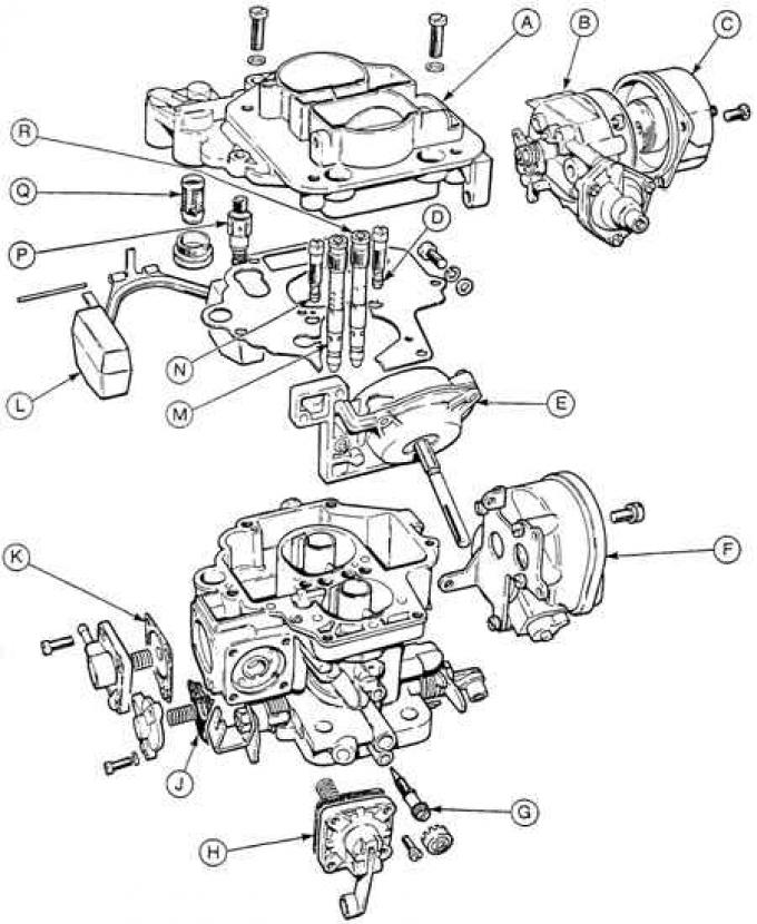
A – carburetor cover, B – starting device housing, C – starting device cover with bimetallic spring, D – idle jet of chamber II, E – vacuum regulator of chamber II, F – idle speed adjustment stepper motor (Weber 85 HF only), G – idle mixture composition adjustment screw (CO content), H – accelerator pump diaphragm, J – full load (full power) enrichment device diaphragm, K – medium load enrichment device diaphragm, L – float, M – emulsion tube of chamber I, N – idle jet of chamber I, P – needle valve, Q – mesh fuel filter, R – emulsion tube of chamber II
Installing a Weber Carburetor Idle Speed Adjustment Stepper Motor
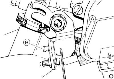
A – stepper motor pusher,
B – mixture throttle lever limiting bolt
Weber 85 HF Carburetor Idle Speed Adjustment
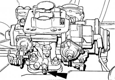
The arrow shows the idle mixture adjustment screw.
The 1.6 dm³ LSD engine uses a two-chamber Weber 84 HF 9510 CA carburetor.
Since the 1985 model, the 2.0 dm³ NET engine has used a Weber 85 HF 9510 CA carburetor (in cars with a manual transmission) or a Weber 8 HF 9510 DA carburetor (in cars with an automatic transmission). The design of the main elements of these carburetors is identical to the Weber 83 HF carburetors previously used in 2.0 dm³ engines.
The Weber 84 HF and 85 HF carburetors contain the following new elements:
- the throttle valve of the II chamber mixture is controlled by the vacuum created in the intake manifold;
- automatic starting device has electric heating (only 85 HF – 2.0 dm³ engine);
- the idle speed is controlled by an electric stepper motor that drives the throttle valve of chamber I. This motor receives control signals from the ignition control module ESC II (only 85 HF – 2.0 dm³ engine).
Checking and adjusting Weber carburetors
The information below concerns only the checking and adjustment of idle speed, as well as the removal and installation of the stepper motor for controlling the throttle valve of the 1st chamber mixture at idle speed of the Weber 85 HF 9510 CA and DA carburetors used in 2.0 dm³ NET type engines.
Removal and installation the stepper motor and basic idle adjustment - 2.0 dm³ engine type NET
Removing and installing the idle speed control stepper motor does not present any particular difficulties.
1. After installation, the basic adjustment should be carried out as follows.
2. Warm up the engine to normal operating temperature, turn off all current consumers and increase the engine speed twice to approximately 2500 rpm.
3. Insert a 1 mm thick feeler gauge between the ends of the plunger (A) (see Fig. Installing a Weber Carburetor Idle Speed Adjustment Stepper Motor) idle speed adjustment stepper motor and the limiting bolt (B) of the mixture throttle lever. The engine idle speed should be 875±25 rpm.
4. If the number of revolutions is not the correct value, then loosen the lock nut of the limiting bolt (B) and, by turning this bolt, achieve the required value of the number of revolutions of the engine idle.
5. Remove the dipstick plate and increase the engine speed at least twice to approximately 2500 rpm.
6. Reinstall the dipstick plate in the appropriate place and check if the engine idle speed is correct.
7. Remove the dipstick plate, check and, if necessary, adjust the CO content in the exhaust gases.
Adjusting the mixture composition (CO content) at idle speed - 2.0 dm³ engine type NET
1. Warm up the engine to normal operating temperature.
2. Connect the tachometer and exhaust gas analyzer.
3. Maintain the engine speed at 3000 rpm for about 30 seconds and release the accelerator pedal.
4. After the readings of both devices have stabilized, read the CO content at idle.
5. If necessary, adjust the CO content using the idle mixture adjustment screw (see Fig. Adjusting the idle speed of the Weber 85 HF carburetor).
6. Install a seal on the idle mixture adjustment screw.
Caution! The idle speed is controlled by the ESC II electronic ignition control module, which controls the stepper motor that rotates the idle mixture throttle valve. This unit is not adjustable.
Weber Carburetor Adjustment Data
| Carburetor | 84 HF 9510 CA (1/2 chamber) | 85 HF 9510 CA (1/2 chamber) | 85 HF 9510 DA (1/2 chamber) |
| Chamber diameter (mm) | 28/ 30 | 30/ 34 | 30/ 34 |
| Diffuser diameter (mm) | 21/ 23 | 25/ 27 | 25/ 27 |
| Main fuel jet | 97/ 110 | 112/ 135 | 110/ 135 |
| Main air jet | 185/ 190 | 165/ 150 | 160/ 150 |
| Emulsion tube | F59/ F22 | F22/ F22 | F22/ F22 |
| Idle fuel jet | 50/ 40 | 45/ 45 | 45/ 45 |
| Float installation - from top edge (mm) | 6,0±0,5 | 8,0±0,5 | 8,0±0,5 |
| Deviation of the starting air damper during operation of the vacuum regulator (mm) | 6,25±0,25 | 9,0 | 8,0 |
| The number of revolutions of accelerated idling (rpm) | 1700±100 | – | – |
| Idle speed (rpm) | 800±25 | 800* | 800* |
| CO content (%) | 1,0±0,25 | 1,0±0,25 | 1,0±0,25 |
* The engine idle speed is controlled by the electronic ignition control module ESC II.