Identification of the rear axle main gear pinion shaft
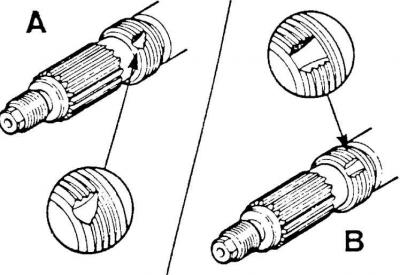
A – old type shaft with right-hand thread,
B – new type shaft with left-hand thread
Rear axle mount
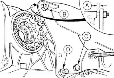
A – gap between crankcase lug and holder plate, B – upper rear mounting bolt, C – lower front mounting bolt, D – lower rear mounting bolt
Rear axle
Main gear pinion
Caution! The pinion of the main gear is integral with the shaft. The changes described below concern the end of this shaft. From November 1982 (manufacturing date code "CA") to July 1983 (manufacturing date code "DS"), when installing the main gear, a special adhesive was applied to the thread as an additional means of preventing the output nut of the main gear shaft from loosening.
Since August 1983 (manufacturing date code "DT"), a change has been made to the design of the journal of the main drive pinion shaft and its nut. The thread on the shaft has been changed from right (old type) to left (new type drive pinions). To facilitate the identification of old and new type shafts, a different notch shape is used on the threaded part of the shaft (see Fig. Identification of the shaft of the main drive pinion of the rear axle).
The method of designating the rear axle housing has also been changed, and instead of a riveted plate, it is now stamped directly on the rear axle housing.
Caution! If it is necessary to unscrew the main gear pinion shaft nut during installation, be sure to use a new nut.
Attention! If an old type nut (with right-hand thread) is used, it is necessary to secure it from unscrewing using a special glue provided for this purpose.
Attention! After tightening the nut, it should be additionally secured against unscrewing with a caulk. This applies to both old and new type nuts. Rear axle fastening
Since September 1984 (production date code "EL"), to eliminate the gap (A) (see fig. Rear axle mounting) that may form between the axle bosses and the mounting elements to the carrier plate, and in particular the bolt (B), U-shaped spacers are used, located between the boss (left and right) and the carrier plate. These spacers have a thickness of: 0.5; 1.0 and 1.5 mm. When installing the rear axle, use a gasket of such thickness that it can move with little effort between the connected elements.
Since May 1986 (production date code "GJ"), the bolts and nuts for fastening the metal-rubber rear axle cushions have been changed. A characteristic feature of the new bolts and nuts is their golden color.
If the rear axle is removed, new type bolts and nuts should be used for installation on all axles.
(The text of the article was copied from the website www.fordbook.ru)