Installation of new metal-rubber bushings connecting the stabilizer to the front suspension arms
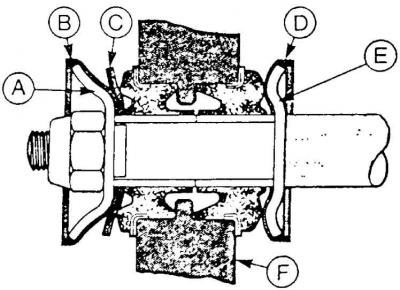
A - front support cup, B - front cup cover, C - rubber support pad, D - rear cup cover, E - rear support cup, F - front suspension arm
Attaching the stabilizer to the arm
Since November 1982 (production date code "SA") casings made of artificial material are used on metal support cups of metal-rubber rings for connecting the stabilizer to the levers.
In the event of knocking in the front suspension while driving at low speed on a relief surface, proceed as follows.
1. Raise the front of the car and secure it.
2. Unscrew the stabilizer mounting nut on the left side.
3. Remove the metal support cup and (if installed) rubber gasket.
4. Pull the lower lever arm forward and remove the rear metal support cup.
5. Wipe rear support cup (E) (see fig. Installation of new metal-rubber bushings connecting the stabilizer to the front suspension arms) and the back of the rear metal-rubber ring connecting the lever and stabilizer.
6. Install shroud (D) on the rear support cup (E) and put on the stabilizer.
7. Thoroughly clean the front support cup (A) and the front part of the front metal-rubber ring.
8. Install rubber support (WITH).
9. Install shroud (IN) on the front support cup (A) and put on the stabilizer.
Attention! If the assembly in question did not have a support rubber gasket, then during the assembly process, such a gasket should be installed between the front metal support cup and the front metal-rubber ring.
10. Screw on the stabilizer mounting nut, but do not tighten it.
11. Do the same on the right side of the car.
12. Lower the car.
13. Tighten the stabilizer mounting nuts on both sides of the suspension to a torque of 70–100 Nm.
Mounting the stabilizer in the supports
Since April 1984 (production date code "EG") until August 1984 (production date code "HER") when installing the stabilizer in the supports, bolts, nuts and supports of a new type are used. In the event of dismantling, it is essential to respect the contents of the original installation.
Nuts of naves of forward wheels
Between December 1982 and January 1983, all versions of the Ford Sierra were fitted with a new type of front wheel hub nut (with left hand thread). In this regard, all nodes of the hubs are marked with letters "L" or "R", meaning, respectively, the left ("L") or right ("R") sides of the car, i.e. side on which they are to be installed.
These changes have been introduced:
- at the Genk plant: December 23, 1982;
- at the Dagenham plant: January 19, 1983;
- at the Cork plant: January 31, 1983.
Other information regarding the technical characteristics, adjustment and repair of the front suspension is given in subsection 9.1.
Visitor comments