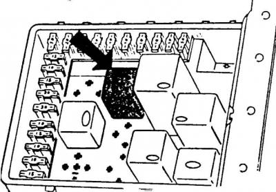
Location of headlight relay in fuse and relay box
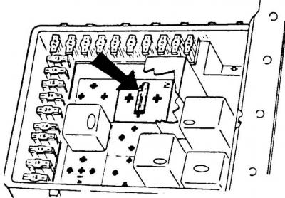
Jumper installed in position "IV" in the fuse and relay box if the vehicle is not equipped with a headlight relay
Changes in the way the electrical wiring harness is connected to the fuse and relay box
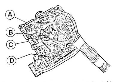
A – connection of the (additionally soldered) gold-colored wire, B – connection of the additional brown ground wire, C – connection of the original yellow wire (from the fuse), D – connection of the brown wire to ground
Since February 1983 (manufacture date code "DK") vehicles of the following versions: Base, L and GL are equipped with a headlight relay, which is located in the "IV" position of the relay in the fuse and relay box (see Fig. Location of the headlight relay in the fuse and relay box).
In case of incorrect switching on of low beam headlights in cars manufactured before the introduction of this relay, the following procedure should be followed.
Cars with a jumper in the "IV" position of the relay in the fuse and relay box
1. Check the wiring harness from the low and high beam headlights.
2. If the fault is not corrected, it is necessary to remove the jumper (see Fig. Jumper installed in position "IV" in the fuse and relay box if the car is not equipped with a headlight relay) and insert the relay in position "IV" (see Fig. Location of the headlight relay in the fuse and relay box).
Cars without jumper and without relay in position "IV" of relay in fuse and relay box
3. Check the wiring harness from the low and high beam headlights.
4. If the fault is not determined, disconnect the battery.
5. Move the interior trim on the left side under the front panel.
6. Pull the plate with the fuse and relay box connectors towards the engine compartment.
7. Cut the yellow wire coming from fuse N16 or 17 at a distance of about 160 mm.
8. Solder a connector (N A83SX-14489-AA) to the end of the wire coming from fuse #16 or 17 and insulate this connector.
9. Prepare two pieces of wire, brown and yellow, with a cross-section of 1.5 mm² and a length of 160 mm.
10. Solder a flat standard contact to the end of the brown wire and a connector (N A83SX-14489-AA) to the other end and insulate them.
11. Solder the connector (N A83SX-14489-AA) to the end of the yellow wire. Solder the other end of this wire to the end of the yellow wire (remaining after cutting) from the original harness and insulate the connections.
12. Connect the end of the yellow wire from fuse N16 or 17 to the connector (C) (see Fig. Changes in the method of connecting the electrical wiring harness to the fuse and relay box) in position "IV" of the relay.
13. Connect additional wires in accordance with Fig. Changes in the method of connecting the electrical wiring harness to the fuse and relay box - brown at points (B) and (D), and yellow at point (A).
[Information for this article was taken from the website: FORDBOOK.RU]