New or replacement shafts are generally supplied in a "protective cage" to prevent the joints from twisting during transport. Remove the cage only after installation and ensure that the seals are not damaged. To remove the drive shafts, first separate the ball joint of the lower wishbone from the pivot bearing. The wishbone remains mounted in this case.


Removing the right shaft
|
ORDER OF EXECUTION |
- Set the parking brake and loosen the wheel hub nut.
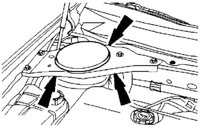
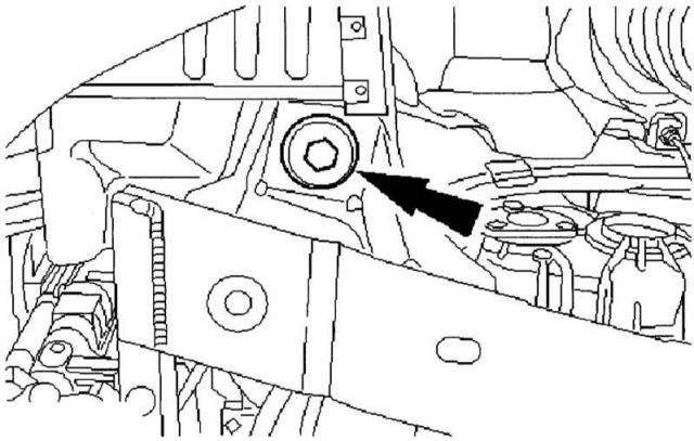
- In the engine compartment, press the locking cap of the right shock absorber bearing (shown by the arrow).
Press the locking cap of the right shock absorber bearing (shown by the arrow). |
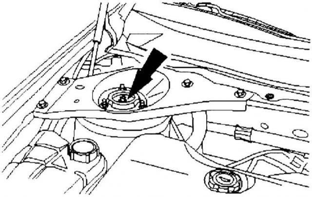
- Turn the shock absorber connecting rod (indicated by the arrow) with an Allen key and loosen the nut in the shock absorber pin about five turns.
Loosen the nut on the shock absorber pin about five turns. |
- Securely support the front of the vehicle on jack stands, block the rear wheel with a chock and remove the right wheel.
- Remove the stabilizer connecting rod (indicated by the arrow) from the shock absorber strut in the wheel well.
Removing the stabilizer connecting rod (indicated by the arrow) from the shock absorber strut. |
- Loosen the wheel hub nut and mark it with a punch. Nuts should be reused as many times as possible.
- Remove the lower wishbone ball joint from the pivot bearing. The wishbone remains mounted in this case. In the event that the wishbone needs to be removed for other work, we will describe this removal separately. In diesel models, the lower engine trim must first be removed. If your Mondeo is equipped with gas-charged headlights, then the headlight range adjuster sensor must be removed from the left lower wishbone.
- Now remove the lower radiator guard (five mounting points) and then secure the lowering side of the subframe using a hydraulic car jack.
- To remove the wishbone, lower the subframe on the side where the drive shaft is to be removed. Then secure the side to be lowered using a hydraulic car jack.
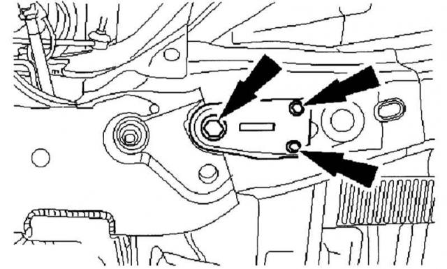
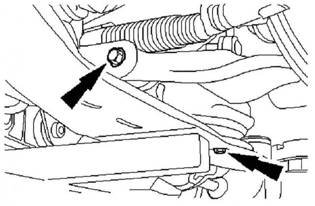
- Now unscrew the rear bolts of the subframe and frame holder (indicated by arrows).
Unscrew the three bolts of the auxiliary frame and frame holder (indicated by arrows). |
- Next, on the opposite side, loosen the rear subframe and frame holder screws about five turns to...
- then completely unscrew the front bolt (indicated by the arrow) on the mounting side. On the opposite side, loosen the screws by about five turns.
On the mounting side, completely unscrew the front bolt (indicated by the arrow), and on the opposite side, loosen the screws by about five turns. |
- To access the rear wishbone bolts, now lower the subframe using a hydraulic jack.
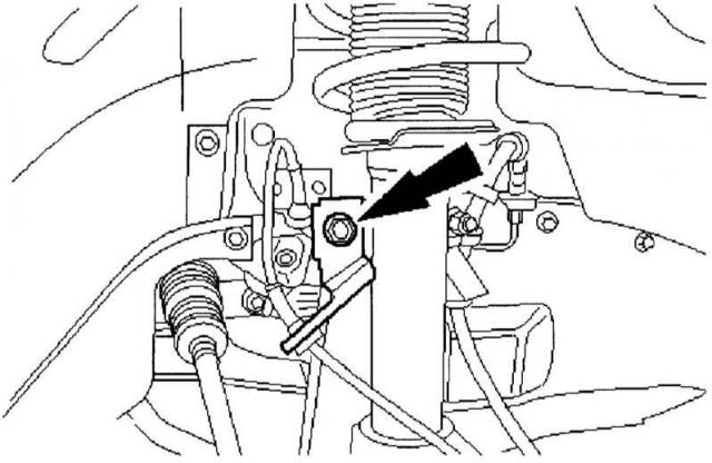
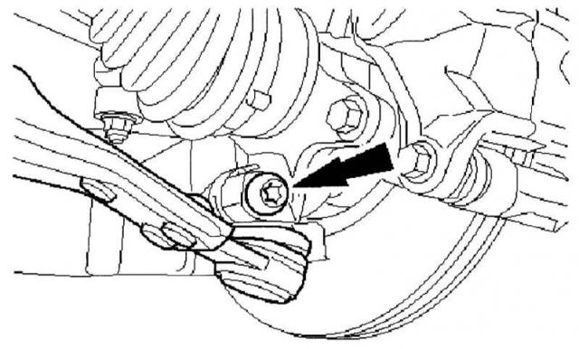
- In order not to damage the rubber bearing of the wishbone, it is necessary to lower the auxiliary frame before releasing the clamping screw of the ball joint (indicated by the arrow).
Loosen the ball joint clamping screw (indicated by the arrow). |
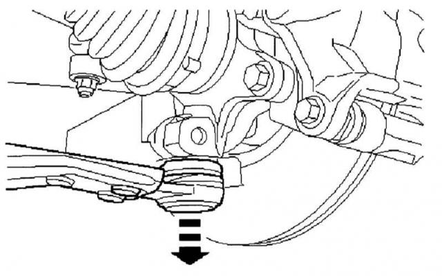
- Protect the bellows on the ball joint from damage with a soft cloth and detach the ball joint from the pivot support (indicated by the arrow). First, remove the heat shield.
Disconnect the ball joint from the swivel support (indicated by the arrow). |
- Remove the lower wishbone (arrow) and use new screws and nuts for installation.
Removing the lower wishbone (indicated by the arrow), dispose of the old screws and nuts after removal. |
- Now support the drive shaft, as the maximum permissible bending angle of the inner joint should not exceed 18° and the outer joint 45°. If this happens, the joint will be damaged.
- Pull the drive shaft off the intermediate shaft with a suitable puller, set it aside and secure it. Remove the retaining ring first and discard it.
- Now use a suitable three-arm puller to pry the drive shaft out of the wheel hub.
|
|
Installation of the right shaft
|
ORDER OF EXECUTION |
- First of all, replace all self-locking nuts and lightly lubricate the axle shaft threads and splined joint with grease before installation.
- Support the new drive shaft so that its joints do not twist and place it under the front of the vehicle.
- Place the shaft on the intermediate shaft and secure it with a new retaining ring.
- Press the outer camshaft onto the "pre-lubricated" splined connection of the wheel hub. If necessary, help yourself with lightly targeted blows of a hammer (rubber mallet) on the wheel hub. Once enough threads have appeared, pull the camshaft completely together with the help of the wheel hub nut.
- Don't tighten the nut completely yet, but...
- ...first mount the stabilizer connecting rod on the shock absorber strut.
- Then mount the control arm ball joint to the pivot bearing.
- If you have completely removed the wishbone, refit it now with new bolts and nuts. Only tighten the bolts completely when you have your Mondeo back on its wheels.
- When mounting the wishbone on the pivot bearing, do not forget about thermal protection.
- Insert the ball joint mounting screws from the rear and tighten to a torque of 83 N·m.
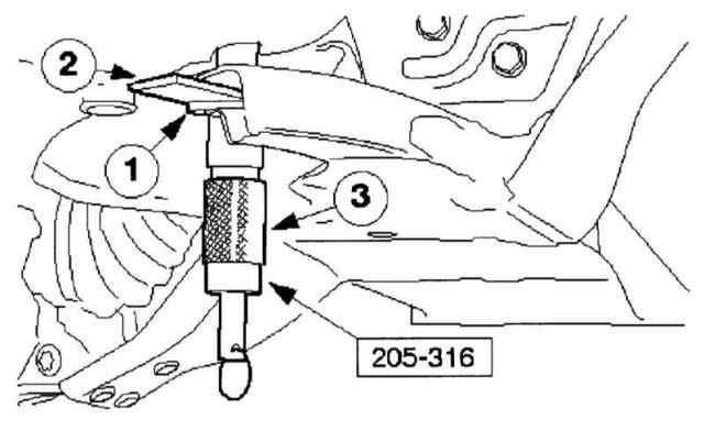
- Now align the subframe by pressing it out. This is a temporary measure: Ford workshops use a special tool (205-316) and suitable washers for this. The professionals do the following:
- They use a shim washer 1 with an internal diameter of 22 mm, an external diameter of 44 mm and a thickness of 5 mm. This washer is placed on top of the lower alignment hole on the subframe. Then the guide pin 2 is inserted through the alignment holes of the subframe and the washer. After that, move the fastening plate 3 along the washer into the groove of the special tool and tighten the guide pin sleeve.
Subframe alignment: For professionals only.
1 Washer, 2 Guide pin, 3 Mounting plate. |
By aligning in this way, you insert the subframe and frame holder screws. When tightening the screws (outer 10 Nm, inner 142 Nm), the subframe should not move. Now insert the front screws and tighten them to 142 Nm. After this, the subframe can no longer be moved. Lower the hydraulic jack and remove the special tool together with the U-washer. Place the vehicle on its wheels and first tighten the wheel hub nut to a torque of 290 Nm. Now tighten the front wishbone bolt to 80 Nm plus 60° and the rear wishbone nut to 90 Nm plus 60°. Complete all work in reverse order. Tighten the connecting rod nut to 59 Nm. Test drive your Mondeo and check that it drives straight and that the steering wheel returns the same in both directions. If not, the car must be measured. If the test drive went smoothly, then finally check all screw connections for tightness. |
|
Dismantling the left shaft
|
ORDER OF EXECUTION |
- Perform the same steps as for removing the right drive shaft up to point F
- Now support the drive shaft, as the maximum permissible bending angle of the inner joint should not exceed 18° and the outer joint 45°. If this happens, the joint will be damaged.
- Remove the safety ring from the gearbox side and dispose of it. Now pull the drive shaft out of the gearbox, making sure not to damage the sealing ring of the radial shafts in the gearbox housing, and carefully lower the shaft. Drain the leaking transmission oil into a clean container and, after repairs, drain it back into the gearbox using a special can.
- To prevent road grime from getting inside, cover the transmission filler neck with a clean rag.
- Now use a three-arm puller to pry the drive shaft out of the wheel hub.
|
|
Mounting the left shaft
|
ORDER OF EXECUTION |
- Be sure to replace all self-locking nuts and lightly lubricate the axle shaft threads and splined joint before installation.
- Insert the new shaft into the gearbox first.
- Then carry out the installation as described in this procedure for the right drive shaft. Afterwards, do not forget to check the transmission oil level.
|
|
Removing the intermediate shaft
|
ORDER OF EXECUTION |
- Proceed in the same manner as in the "Removing the Right Drive Shaft" section up to step 18.
- Separate both drive shafts and set both shafts aside in a safe place. Make sure that their joints are not twisted.
- When installing, use a new safety ring. And then everything depends on the type of engine.
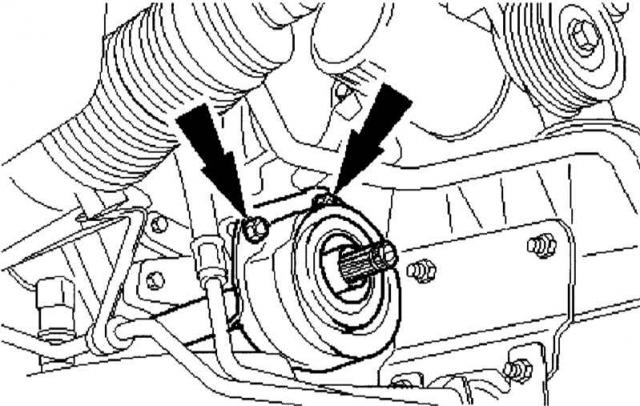
Mondeo with Duratec-VE engine - Remove the nuts on the intermediate bearing cover (indicated by arrows) and dispose of them together with the cover. Drain the leaking transmission oil into a clean container for reuse.
Remove the locknuts on the intermediate bearing cover (indicated by arrows) and dispose of them together with the cover. |
- Pull the shaft out of the gearbox and cover the hole with a clean rag. Be careful not to damage the sealing ring of the radial shafts in the gearbox housing.
Mondeo with DuraTorg-DI engine
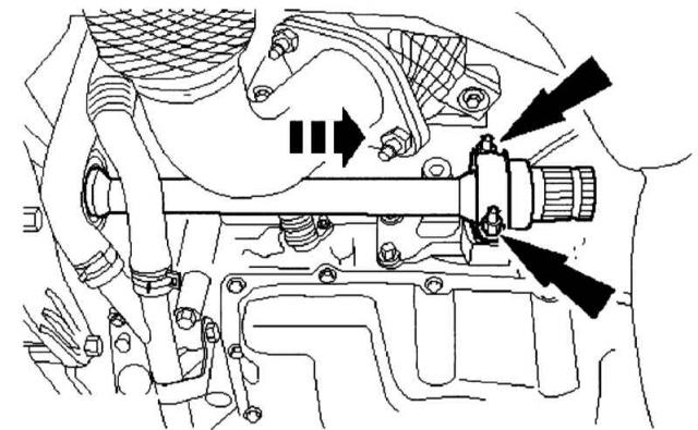
- Remove the nuts on the intermediate bearing cover (indicated by arrows) and dispose of them together with the cover. Drain the leaking transmission oil into a clean container for reuse.
Remove the locknuts on the intermediate bearing cover (indicated by arrows) and dispose of them together with the cover. |
Mondeo with Duratec-NE engine
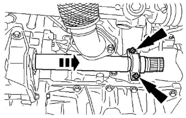
- Remove the nuts on the intermediate bearing cover (indicated by arrows) and dispose of them together with the cover. Drain the leaking transmission oil into a clean container for reuse.
Remove the locknuts on the intermediate bearing cover (indicated by arrows) and dispose of them together with the cover. |
|
|
Installation of intermediate shaft
|
ORDER OF EXECUTION |
- Mount the intermediate shaft taking into account the car engine in the reverse order. Tighten the intermediate bearing with a force of 25 Nm. Pay attention not to damage the old sealing ring of the radial shafts. It will be even better if you install a new ring.
- for installation, also use new lock nuts and bearing cover.
- Complete the installation of the intermediate shaft depending on the engine type in reverse order and proceed further.
|
|
(Information for this article was taken from the website FORDBOOK.ru)