Note: Read the description of the entire procedure, and especially the instructions for lifting equipment. Depending on your funds, you can first remove the power block, and then undock the engine from the transmission at the workbench (chapter 2).
Withdrawal
1. Disconnect the negative battery cable (chapter 5 paragraph 1). You can remove the battery for better access.
2. If necessary, remove the hood to improve access and installation of the lifting device (chapter 11).
3. Raise the heatsink and secure it in the raised position by inserting cotter pins into the holes in the top support pins. This is to hold the radiator when removing the subframe.
4. Remove the air flow meter and intake duct (chapter 4).
5. Remove the air cleaner assembly (chapter 4).
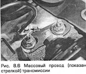
6. Disconnect the mass wire from the transmission (see fig. 8.6).
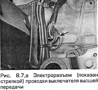
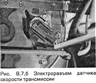
7. Disconnect the wiring connectors of the high gear switch, control device and transmission speed sensor (see fig. 8.7, a, b).
8. Disconnect the selector cable end switch from the lever on the transmission. Turn out a bolt and remove an arm.
9. Apply the parking brake, raise the front end and place it on supports. Remove the front wheels.
10. Remove the wheel arch locker from the right side of the car (chapter 11).
11. Remove the accessory drive cover (Chapter 1).
12. Disconnect the anti-roll bar link from the suspension strut. To do this, working alternately on each side of the car, unscrew the nut of each even. Note that the brake hose bracket is attached to the link stud.
13. Pull out cotter pins, and then turn away nuts of fastening of a limit switch of each cross steering draft to a rotary fist. Release the ball joints from the steering knuckle arms with a ball joint puller.
14. Working alternately on each side of the vehicle and taking into account which side the front suspension lower arm ball joint clamp bolt is inserted, remove the bolt. Take it off your fist. Press the ball joint away from the steering knuckle. If this is difficult to do, open the joint with a power screwdriver or pry bar. Do not damage the ball joint seal.
15. Remove the front bottom cover from the bottom of the radiator. To do this, release it from the latches and unscrew the fixing bolts.
16. Drain the liquid from the cooling system (Chapter 1).
17. Disconnect the oxygen sensor wiring connector. Then unfasten the wiring harness from the rear engine mount.
18. Disconnect a vacuum hose from the filter of system of afterburning of fuel.
19. Remove the entire exhaust system (chapter 4).
20. On models with an air conditioning system, remove the bolts securing the evaporator to the subframe and tie the evaporator.
21. Turn out bolts of fastening of the steering mechanism to a stretcher. It is difficult to get to them with a normal key. It is advisable to use a Ford crank adapter (chapter 10).
22. Turn out bolts of a back support of the power block from a stretcher.
23. Turn out the central bolt from a forward support of the engine. Disconnect the afterburner filter from the bracket located on the support.
24. Turn out bolts of an arm of a radiator from a stretcher.
25. Together with an assistant, supporting the subframe, unscrew the bolts securing the steering hydraulic radiator pipes to the subframe. Then remove the subframe bolts and lower it to the ground.
26. Turn out the central bolt from a back support of the power block. Then remove the support bolts from the transmission.
27. Turn away a nut of fastening of the pipeline of a radiator of transmission on its left side. Unfasten the pipeline and slide it to the side. Plug the pipe ends to prevent dirt or dust from getting in.
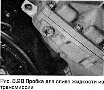
28. Place a container under the transmission. Then remove the drain plug (see fig. 8.28). Finally install and tighten the plug.
29. Insert a pry bar between the left driveshaft inner pivot and the transmission case (placing a thin piece of wood between the case and the mount). Then press the hinge away from the differential. If necessary, tap the mount with the palm of your hand. Be careful not to damage adjacent components and get ready to clean up oil leaks.
30. Support the left drive shaft on a support so that the inner joint does not rotate more than 18° (otherwise it may be damaged).
31. Turn out bolts of fastening of the central bearing of the right leading shaft to the block of cylinders. Remove the heat shield. Then pull the right strut so that the countershaft comes out of the transmission differential. Get ready to clean up oil leaks.
32. Support the right drive shaft on a support so that the inner joint does not rotate more than 18° (otherwise it may be damaged).
33. Turn away a nut of the pipeline of a radiator of transmission in its forward part. Disconnect the pipe and plug its end to prevent dirt or dust from getting in.
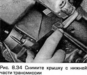
34. Turn out bolts and remove a cover from the bottom part of transmission for access to fastening bolts of the hydrotransformer, (see fig. 8.34).
35. Turn out fixing bolts of the hydrotransformer. For alternate access to the bolts, turn the engine at the crankshaft pulley bolt.
36. If necessary, at this stage the car can be lowered to the ground to connect the lift to the engine. If the engine is suspended from a rod supported by the engine compartment, the vehicle may remain in the raised position.
37. Attach the hoist by attaching the hook to the diagonal engine lifting lugs and hang out the power unit.
38. Disconnect the wiring connectors on the thermostat housing.
39. Disconnect the radiator hoses from the thermostat housing.
40. Turn out bolts and remove the case of the thermostat.
41. Turn out the top bolts of fastening of transmission to the engine.
42. Turn away nuts of an arm of the right support of the engine. Please note that if this support is hydraulic (chapter 2A paragraph 22), then it should not deviate from the vertical by more than 5°.
43. Turn away nuts and remove the left support of the power block from transmission.
44. On models with an air conditioning system, lower the engine until the compressor is below the right cross member.
45. On models without an air conditioning system, lower the transmission until the sleep is opposite the opening located on the left side of the engine compartment.
46. Support the transmission with a jack. Secure it to the jack with chains or with a suitable cradle.
47. Turn out bolts of a starter.
48. Turn out the bottom bolts of fastening of transmission to the engine.
49. Together with an assistant, separate the transmission from the engine, trying not to warp it anyway. so that the clutch friction disc does not take the weight of the transmission. After removing the transmission, remove the bottom cover installed between the transmission and the engine (see fig. 8.49).
50. Lower the transmission to the ground.
Installation
51. Clean the mating surfaces of the faceplate and torque converter.
52. The torque converter must be fully inserted into the transmission. Check this with a ruler mounted on the transmission flange. The distance from the transmission flange to the end of the torque converter shaft must be at least 10 mm (see fig. 8.52).
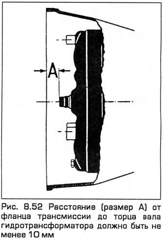
Attention: This is necessary for the mechanical connection of the torque converter to the pump. Incorrect connection causes serious damage!
53. Raise the transmission, fixed on the jack, to the working position, and then carefully dock it with the back of the faceplate. In this case, the torque converter must maintain its position.
54. Insert bolts of fastening of transmission to the engine and tighten them.
55. Insert and tighten the starter bolts.
56. Remove the mobile jack.
57. Install the left and right power block supports and lightly tighten their nuts.
58. Install the thermostat housing and tighten its bolts.
59. Attach the radiator hoses to the thermostat housing.
60. Connect the two wiring connectors on the thermostat housing.
61. Insert all the torque converter bolts and tighten them to the required torque by turning the engine to do this.
62. Install the cover on the bottom of the transmission and tighten its bolts.
63. Install the transmission radiator pipe in front of it and tighten the union nut.
64. Install the right drive shaft and intermediate shaft together with the heat insulating casing (chapter 8).
65. Install the left drive shaft (chapter 8).
66. Install the transmission radiator pipeline in its left part and tighten the union nut. Secure the pipeline with clamps.
67. Install the rear support of the power unit on the transmission without tightening the center bolt.
68. Install and align the subframe (chapter 2B paragraph 4). Tighten the bolts to the required torque.
69. Establish on a subframe pipelines of a radiator of a hydrosystem of a steering and tighten bolts.
70. Install the radiator bracket on the subframe and tighten the bolts.
71. Install the center bolt into the front engine mount hand tight.
72. Install the afterburner filter.
73. Install the rear support of the power unit on the subframe and tighten the bolts.
74. Disconnect the hoist from the engine.
75. Install the engine mount bolts and tighten them (chapter 2A, paragraph 22).
76. Install the steering gear on the subframe and tighten the bolts.
77. On models with an air conditioning system, install the evaporator on the subframe and tighten the bolts.
78. Install the exhaust system (chapter 4).
79. Connect the vacuum hose to the afterburner filter.
80. Attach the oxygen sensor harness and secure it to the rear engine mount.
81. Install the bottom cover under the radiator.
82. Install the ball joint of each lower front suspension arm on the steering knuckle and tighten the clamp bolt (chapter 10).
83. Install the trailer of each tie rod on the steering knuckle (chapter 10).
84. Establish connecting links of the stabilizer of cross stability on racks of a suspension bracket and tighten nuts.
85. Establish a cover of a drive of auxiliary units and poker of the right wheel arch.
86. Install the front wheels and lower the car to the ground. Tighten wheel nuts.
87. Install the selector cable and bracket and tighten the bolts.
88. Connect the electrical connector of the high gear switch..
89. Connect the ground wire to the transmission and tighten the bolt.
90. Install the air cleaner assembly.
91. Install air mass meter and intake duct (chapter 4).
92. Pull out the cotter pins that secure the radiator.
93. Install the hood if it has been removed.
94. Install the battery, if it was removed, and connect its wires.
95. Adjust the selector cable (paragraph 3).
96. Adjust the selector lever position sensor (paragraph 6).
97. Fill transmission and check fluid level (Chapter 1).
98. Fill the cooling system (Chapter 1).
99. After the engine has run a little, check the fluid level again and, if necessary, refuel the transmission (Chapter 1).
100. Check the car on a trip by controlling the operation of the transmission.
Visitor comments