Contents: Removal ↳ Installation and adjustment ↳
Removal
1. Remove the air flow meter and chute (chapter 4) to access the sensor, which is mounted on the top of the transmission.
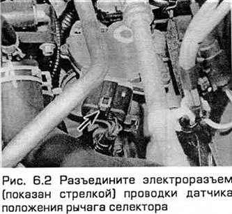
2. Disconnect the electrical wiring connector (see Fig. 6.2).
3. Unscrew the mounting bolts and remove the sensor.
Installation and adjustment
4. Installation - in the reverse order of removal. Before tightening the bolts, the sensor must be set as follows.
5. Set the selector to position N.
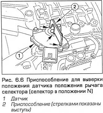
6. The device for adjusting the position of the sensor is a metal plate with projections that should fit into the slots of the sensor and shaft (see Fig. 6.6). You can make such a device yourself or use a ruler for adjustment.
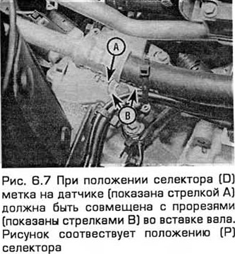
7. Rotate the sensor on the shaft so that the slots in the sensor housing and the plastic shaft insert are aligned. Then tighten the bolts and remove the device. Perform the next step of the test. Move the selector to position D and make sure that the D mark on the sensor is aligned with the slots in the shaft insert (see Fig. 6.7).